A broadband 360° tunable microwave signal phase shifting device and method
A microwave signal and phase-shifting technology, applied in electromagnetic wave transmission systems, electrical components, transmission systems, etc., can solve problems such as reducing the stability of phase-shifting signals, increasing the complexity, and limiting the operating frequency range, achieving convenient control and phase-shifting. The effect of strong stability and simple device structure
- Summary
- Abstract
- Description
- Claims
- Application Information
AI Technical Summary
Problems solved by technology
Method used
Image
Examples
Embodiment 1
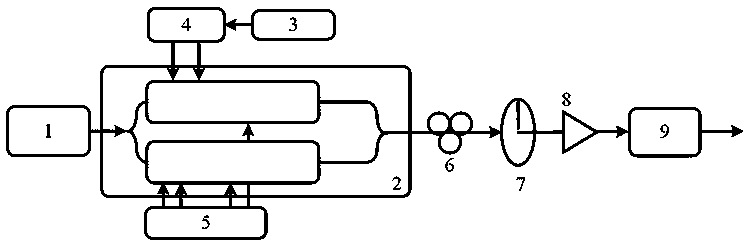
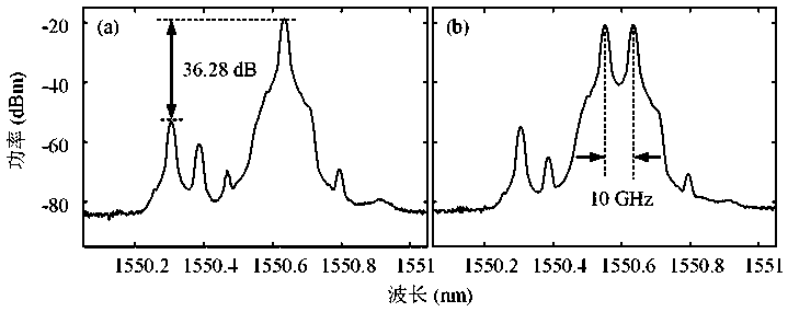
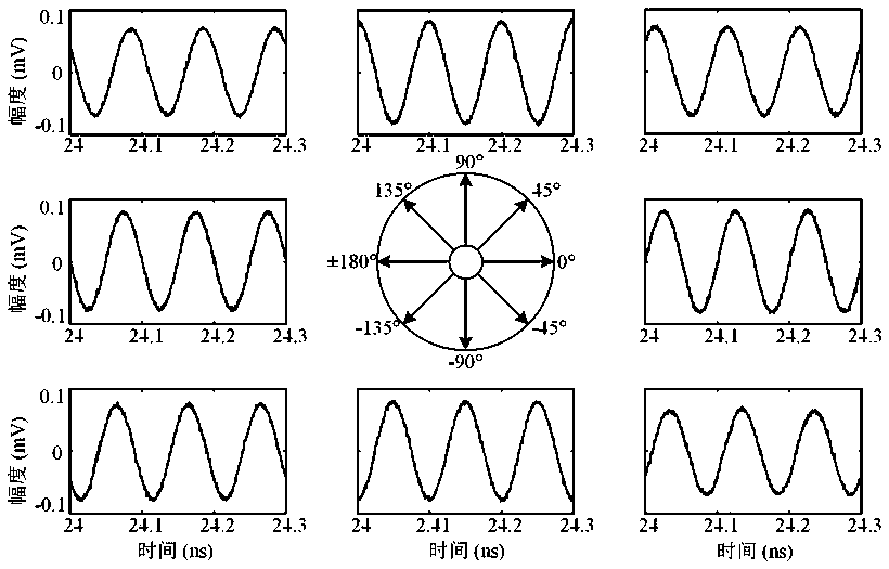
[0055] In this embodiment, the wavelength of the optical signal output by the laser is 1550.55 nm. Adjust the DC bias voltage so that the two sub-MZMs of the sub-DP-MZM that input the microwave signal at the RF input port are biased at the minimum transmission point, and the main MZM is biased at the orthogonal transmission point; make the sub-DP of the RF input port input the DC signal - The two sub-MZMs of the MZM are respectively biased at the maximum transmission point and the minimum transmission point, and the main MZM is biased at the orthogonal transmission point. In this embodiment, the frequency of the input microwave signal is 10 GHz. figure 2 (a) is the spectrogram of the DP-MZM output optical signal of the input microwave signal. It can be seen that the suppressed carrier single sideband modulation has been realized. Except for one first-order optical sideband, the rest of the optical sidebands are well suppressed , the rejection ratio is greater than 36.28dB; ...
Embodiment 2
[0057] In this embodiment, the wavelength of the optical signal output by the laser is 1550.55 nm. Adjust the DC bias voltage so that the two sub-MZMs of the sub-DP-MZM that input the microwave signal at the RF input port are biased at the minimum transmission point, and the main MZM is biased at the orthogonal transmission point; make the sub-DP of the RF input port input the DC signal - The two sub-MZMs of the MZM are respectively biased at the maximum transmission point and the minimum transmission point, and the main MZM is biased at the orthogonal transmission point. In this embodiment, the frequency of the input microwave signal is 18 GHz. Figure 4 (a) is the spectrogram of the DP-MZM output optical signal of the input microwave signal. It can be seen that the suppressed carrier single sideband modulation has been realized. Except for one first-order optical sideband, the rest of the optical sidebands are well suppressed , the rejection ratio is greater than 29.82dB; ...
Embodiment 3
[0059] In this embodiment, the wavelength of the optical signal output by the laser is 1550.55 nm. Adjust the DC bias voltage so that the two sub-MZMs of the sub-DP-MZM that input the microwave signal at the RF input port are biased at the minimum transmission point, and the main MZM is biased at the orthogonal transmission point; make the sub-DP of the RF input port input the DC signal - The two sub-MZMs of the MZM are respectively biased at the maximum transmission point and the minimum transmission point, and the main MZM is biased at the orthogonal transmission point. In this embodiment, the frequency of the input microwave signal is 23 GHz. Image 6 (a) is the spectrogram of the DP-MZM output optical signal of the input microwave signal. It can be seen that the suppressed carrier single sideband modulation has been realized. Except for one first-order optical sideband, the rest of the optical sidebands are well suppressed , the rejection ratio is greater than 28.47dB; ...
PUM
 Abstract
Description
Claims
Application Information
 - Generate Ideas
- Intellectual Property
- Life Sciences
- Materials
- Tech Scout
- Unparalleled Data Quality
- Higher Quality Content
- 60% Fewer Hallucinations
Browse by: Latest US Patents, China's latest patents, Technical Efficacy Thesaurus, Application Domain, Technology Topic, Popular Technical Reports.
© 2025 PatSnap. All rights reserved.Legal|Privacy policy|Modern Slavery Act Transparency Statement|Sitemap|About US| Contact US: help@patsnap.com


