
a motor winding

A technology of motor windings and coils, applied in the field of motor windings, can solve the problems of increasing the length of end windings, increasing winding materials and winding losses, reducing generator efficiency, etc., achieving the effect of reducing winding materials, reducing winding losses, and reducing impact

Active Publication Date: 2020-03-17
SHANGHAI ELECTRIC WIND POWER GRP CO LTD +1
View PDF3 Cites 0 Cited by
  • Summary
  • Abstract
  • Description
  • Claims
  • Application Information

AI Technical Summary

Problems solved by technology

Because the adjacent slots are in different phases, the windings of the same phase must cross other windings of different phases. The three coils overlap at the end, and every three coils at the end of the winding need to avoid each other, so the three coils are designed separately. different inclination angles, which makes the end shapes of the three coils also different, which correspondingly increases the length of the end windings, thereby increasing the winding material and winding loss, and reducing the efficiency of the generator

Method used


Image

  • a motor winding
  • a motor winding
  • a motor winding

Examples


Embodiment Construction

[0021] based on the following Figure 3 ~ Figure 7 , specifically describe the preferred embodiment of the present invention.

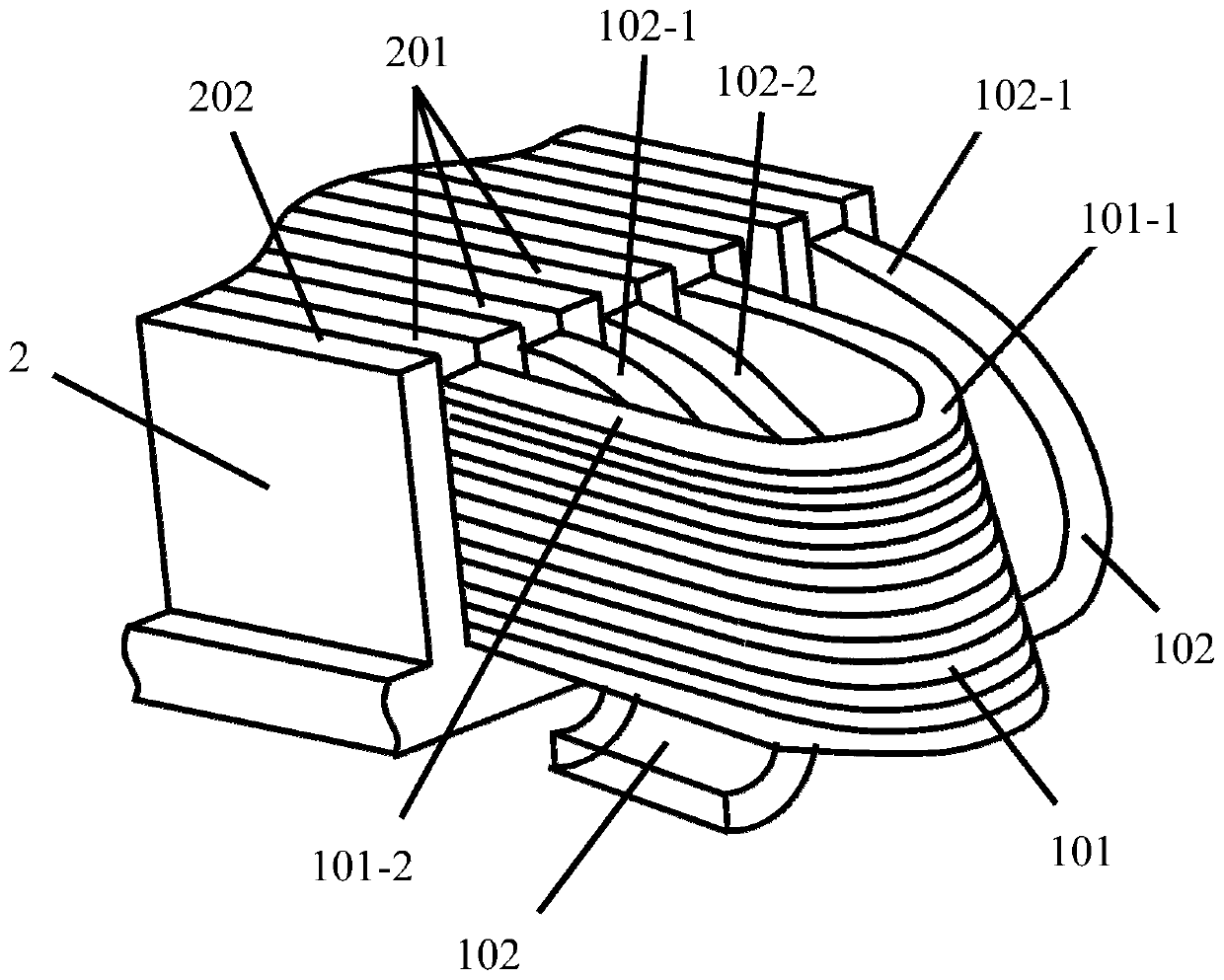
[0022] Such as image 3 and Figure 4 As shown, the present invention provides a motor winding, including: a stator 2 and a plurality of A-phase coils, a plurality of B-phase coils and a plurality of C-phase coils arranged on the stator 2 overlapping each other. The A-phase coils, B-phase coils and C-phase coils all include first-type coils 101 and second-type coils 102, that is, the first-type coils 101 can be set as A-phase coils, B-phase coils and For the C-phase coil, the second type of coil 102 can be configured as an A-phase coil, a B-phase coil, and a C-phase coil. A-phase coils, B-phase coils and C-phase coils overlap each other in pairs, that is, A-phase coils overlap with B-phase coils and C-phase coils respectively, B-phase coils overlap with A-phase coils and C-phase coils respectively, and C-phase coils overlap with A-phase coils and C...


PUM


Abstract

The invention discloses a motor winding. The motor winding comprises a stator and a plurality of A-phase coils, a plurality of B-phase coils and a plurality of C-phase coils which are mutually overlapped and arranged on the stator, wherein the A-phase coils, the B-phase coils and the C-phase coils are overlapped mutually in pairs; first type of coils and second type of coils are contained in the A-phase coils, the B-phase coils and the C-phase coils respectively; the angles of the first type of coils at the end of the motor winding are maintained to be parallel to the axial direction of the stator; the second type of coils are of inclined angles relative to the axial direction of the stator at the end of the motor winding; and the inclined angles guarantee that the second type of coils getround the first type of coils adjacent to the second type of coils in the minimum lengths. Only the two types of coils are adopted for mutual overlapping, mutual overlapping of the two types of coilsis realized at the ends of the coils in a compact manner, and the lengths of the ends of the coils are obviously reduced, so that the winding material is reduced, the winding loss is also reduced while the cost is reduced, the efficiency of a power generator is improved, the occupancy rate of the winding end space is further reduced, and the influence of the end winding on a heat dissipation airflue is reduced.

Description

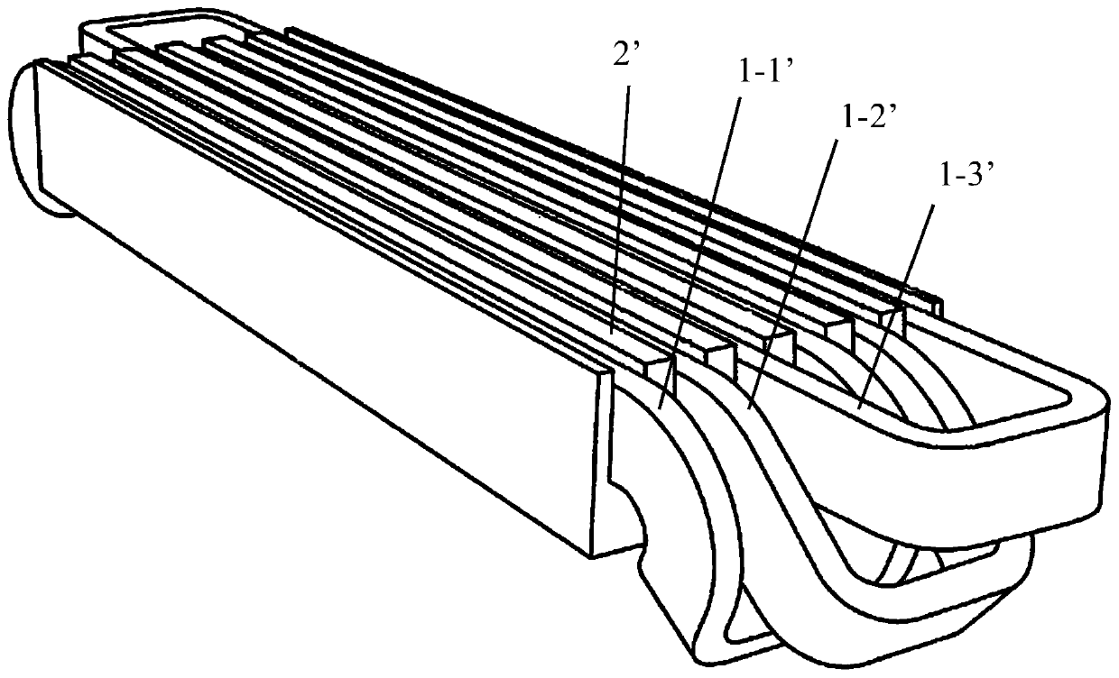
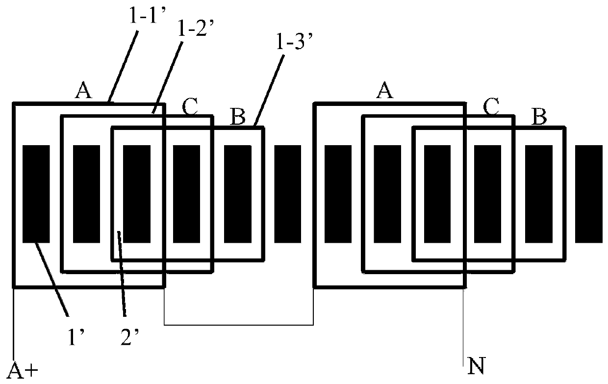
technical field [0001] The invention relates to a motor winding. Background technique [0002] figure 1 and figure 2 Shown is the structure of the end winding of a traditional permanent magnet direct drive wind power generator. The coil is arranged in the winding slot, and the two sides of the slot 2' are teeth 1', in which every three coils form a group, and the first coil 1-1 ', the second coil 1-2' and the third coil 1-3' respectively correspond to the three phases ABC. Because the adjacent slots are in different phases, the windings of the same phase must cross other windings of different phases. The three coils overlap at the end, and every three coils at the end of the winding need to avoid each other, so the three coils are designed separately. Different inclination angles make the end shapes of the three coils also different, which increases the length of the end windings accordingly, thereby increasing the winding material and winding loss, and reducing the effi...

Claims


Application Information

Patent Timeline
Patent Type & Authority Patents(China)
IPC IPC(8): H02K3/04H02K3/28
CPCH02K3/04H02K3/28
Inventor 吴立建方攸同孟迎周翔
Owner SHANGHAI ELECTRIC WIND POWER GRP CO LTD
Learn More