
River water quality floatation monitoring device

A monitoring device and water quality technology, applied in two-dimensional position/channel control, testing water, transportation and packaging, etc., can solve the problems of no public floating structure, easy damage of equipment, uncertain location, etc., and reduce the cost of manual cleaning The effect of frequency

Inactive Publication Date: 2018-02-09
顾梦君
View PDF5 Cites 13 Cited by
  • Summary
  • Abstract
  • Description
  • Claims
  • Application Information

AI Technical Summary

Problems solved by technology

The water quality monitoring floating device of the water environment in the prior art is shown in the patent CN206258450U, which can float and monitor the general situation of the water body, but this patent does not disclose a specific floating structure, nor does it provide an effective shockproof and cleaning structure for the floating device , causing the equipment to be easily damaged after a collision, and requires frequent manual cleaning, so it is not suitable for use in inland rivers
[0003] At the same time, the existing water quality monitoring floating devices are all drifting with the river water. After the river flows, the position of the water quality monitoring floating device is uncertain, and it needs to be salvaged manually, or it is fixed in one place, and it is impossible to perform water quality testing in multiple places at the same time.

Method used


Image

  • River water quality floatation monitoring device
  • River water quality floatation monitoring device
  • River water quality floatation monitoring device

Examples


Embodiment 1

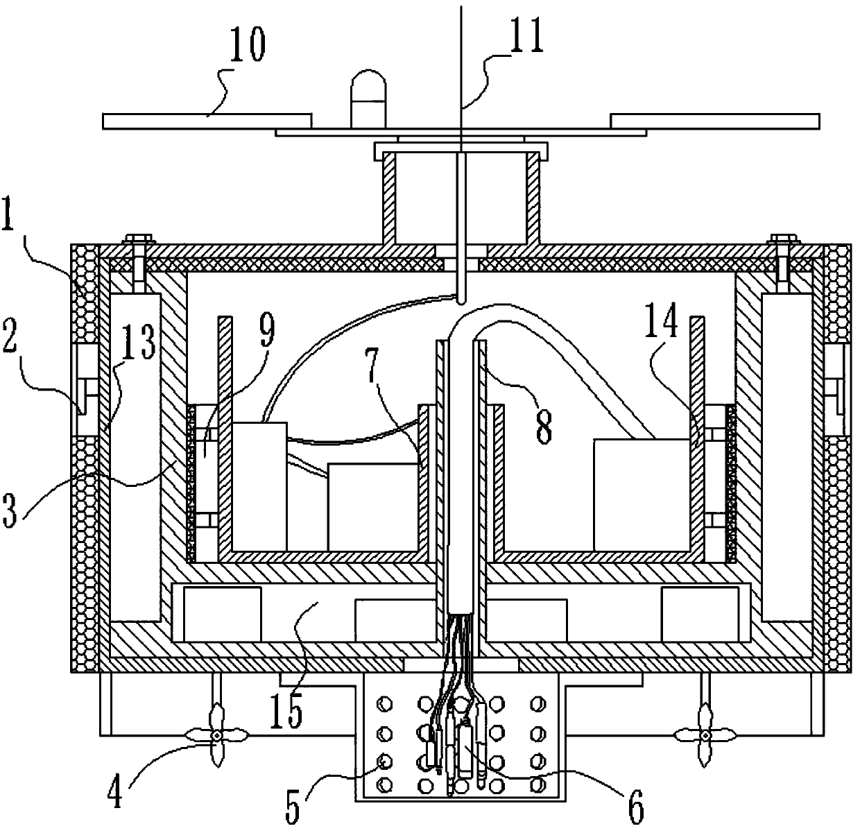
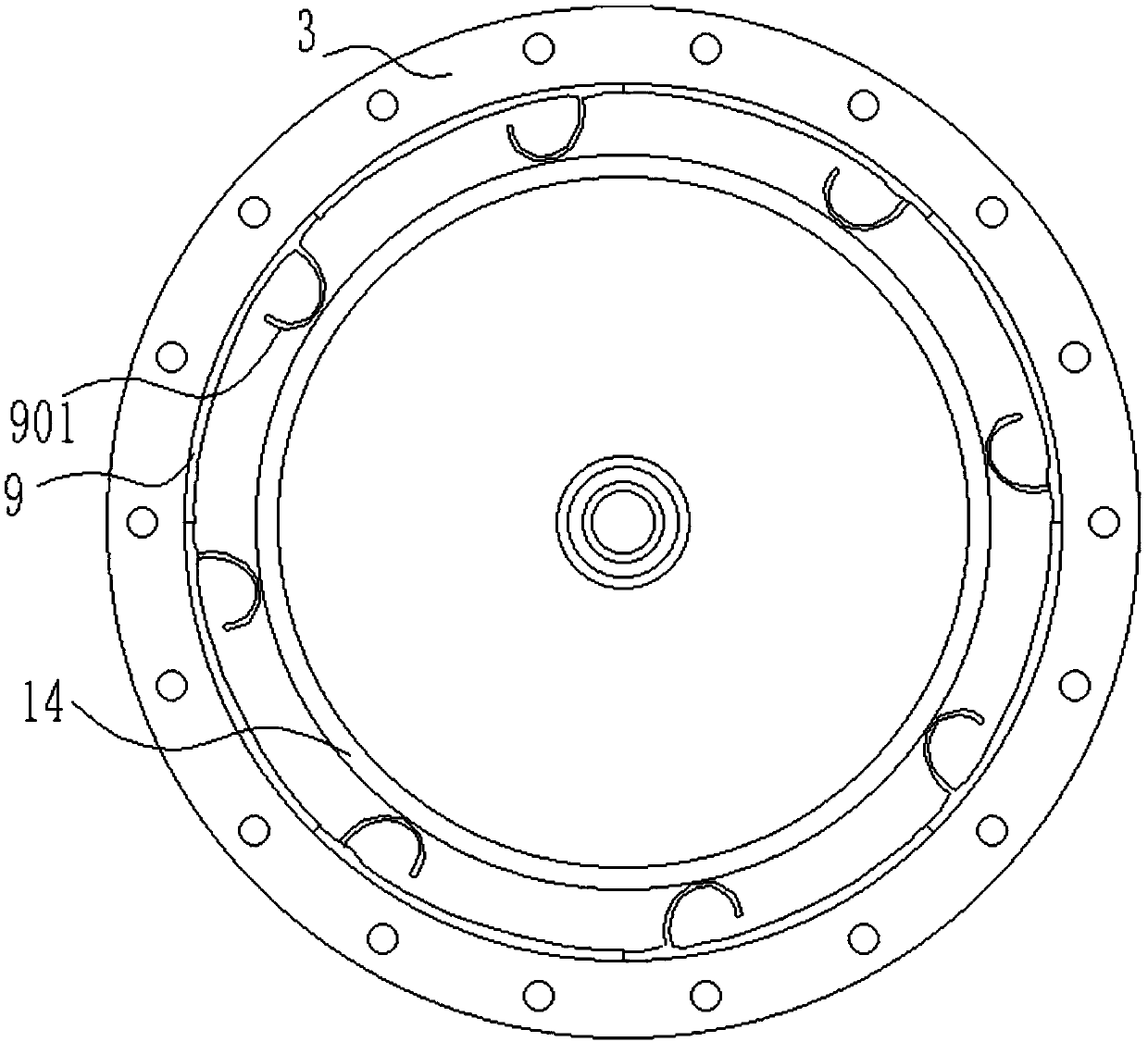
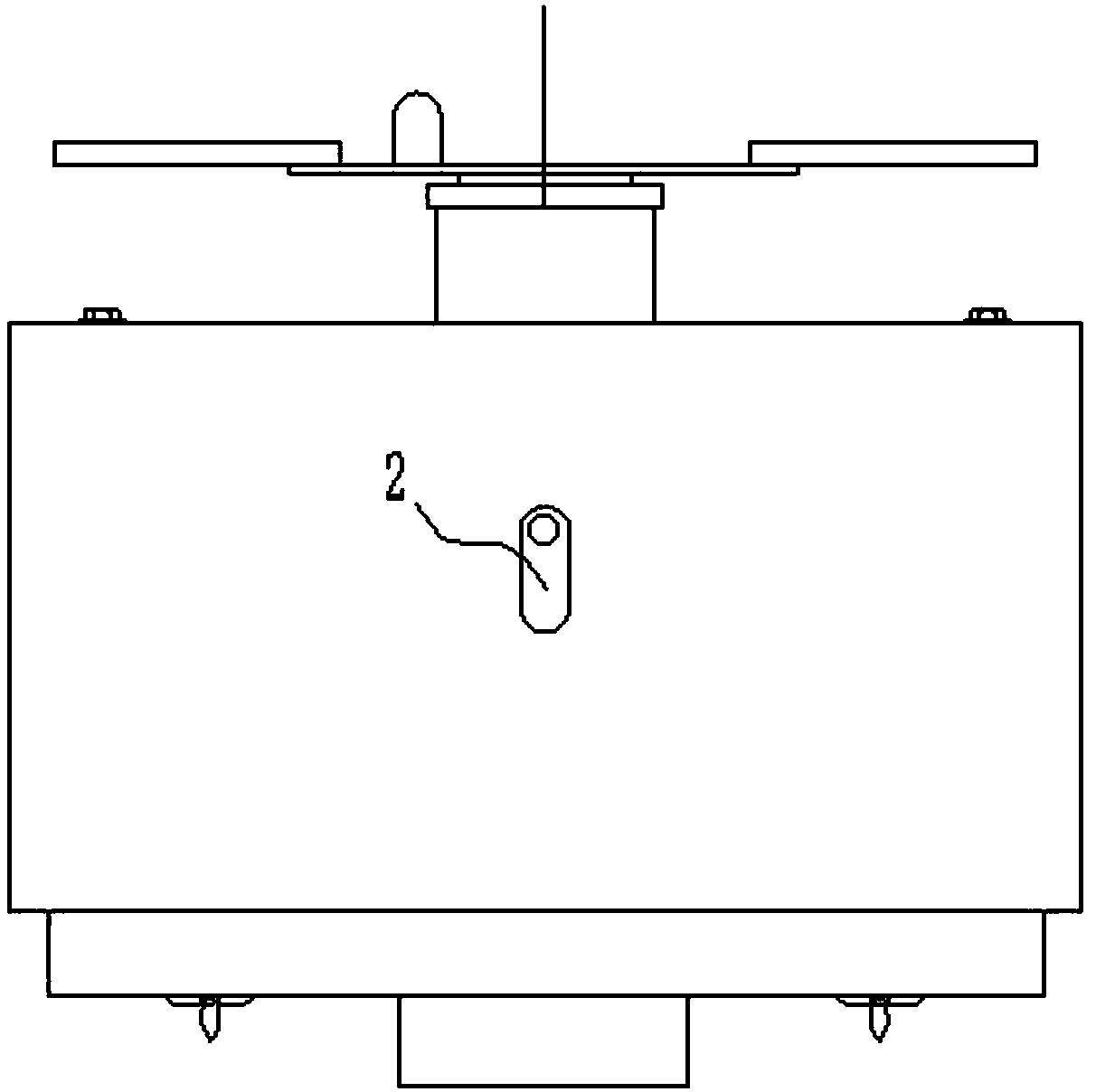
[0030] A floating monitoring device for river water quality, comprising a buoy 13, a support barrel 3 positioned in the buoy 13, an inner barrel 14 in the support barrel 3, a storage battery, a controller, a signal transmitter and a signal receiver, a memory and a battery are arranged in the inner barrel 14. Positioning device, the river map is stored in the memory, the water quality sensor 6 is also provided under the buoy 13, the water quality sensor 6 is connected to the controller in the inner bucket 14, and the propulsion blade 4 and rudder are also provided at the bottom of the buoy 13, so The propulsion blades 4 are located on both sides of the water quality sensor 6, and the rudder 12 is located behind the water quality sensor 6.

[0031] The bottom of the support bucket 3 is provided with a propulsion installation chamber 15, which is provided with a motor and a steering gear that drive the propulsion blade 4 to operate, and 4 cameras are arranged at equal angles on th...


PUM


Abstract

The invention relates to a water quality monitoring device, and discloses a river water quality floatation monitoring device which includes a buoy, a supporting barrel located in the buoy, and an inner barrel inside the supporting barrel. The inner barrel is internally provided with a storage battery, a controller, a signal transmitter, a signal receiver, a memory and a positioning device. A riverway channel is stored in the memory, and a water quality sensor is also arranged below the buoy. The water quality sensor is connected to the controller in the inner barrel, and propulsion paddles anda rudder are also arranged at the bottom of the buoy. The propulsion paddles are located on the two sides of the water quality sensor, and the rudder is located at the rear of the water quality sensor. Due to the adoption of the technical scheme, the river water quality floatation monitoring device can automatically run to a river surface of a designated site to automatically monitor water quality. The river water quality floatation monitoring device is further provided with an anticollision buffer and self-cleaning device, self-cleaning can be performed while internal electronic devices canbe effectively protected, and manual cleaning efficiency is reduced.

Description

technical field [0001] The invention relates to a water quality monitoring device, in particular to a float monitoring device for river water quality. Background technique [0002] The problem of water pollution has become an important factor affecting the quality of life and happiness of the people. It is of great significance to obtain water environment parameters and research and develop water quality monitoring devices. The water quality monitoring floating device of the water environment in the prior art is shown in the patent CN206258450U, which can float and monitor the general situation of the water body, but this patent does not disclose a specific floating structure, nor does it provide an effective shockproof and cleaning structure for the floating device , causing the equipment to be easily damaged after a collision and requires frequent manual cleaning, so it is not suitable for use in inland rivers. [0003] At the same time, the existing water quality monitor...

Claims


Application Information

Patent Timeline
IPC IPC(8): G01N33/18G05D1/00G05D1/02B63B35/00B63H1/14
Inventor 顾梦君
Owner 顾梦君
Learn More