
Dual-frequency high-gain yagi antenna

A Yagi antenna and high-gain technology, which is applied in the field of dual-band Yagi antennas, can solve problems such as gain reduction and high gain, and achieve the effects of easy processing, simple antenna structure, and low cost

Inactive Publication Date: 2018-02-06
SYSU CMU SHUNDE INT JOINT RES INST +2
View PDF5 Cites 8 Cited by
  • Summary
  • Abstract
  • Description
  • Claims
  • Application Information

AI Technical Summary

Problems solved by technology

However, the advantages of traditional dual-band or multi-band Yagi antennas can only be realized in a narrow single specific frequency band, and the gain will be greatly reduced once it is far away from a specific frequency band.
Therefore, even if the Yagi antenna works on multiple frequency bands, its high gain can only appear in a narrow specific frequency band.

Method used


Image

  • Dual-frequency high-gain yagi antenna
  • Dual-frequency high-gain yagi antenna
  • Dual-frequency high-gain yagi antenna

Examples


Embodiment Construction

[0023] The drawings are for illustrative purposes only, and should not be construed as limitations on this patent; in order to better illustrate this embodiment, some parts in the drawings will be omitted, enlarged or reduced, and do not represent the size of the actual product;

[0024] For those skilled in the art, it is understandable that some well-known structures and descriptions thereof may be omitted in the drawings. The technical solutions of the present invention will be further described below in conjunction with the accompanying drawings and embodiments.

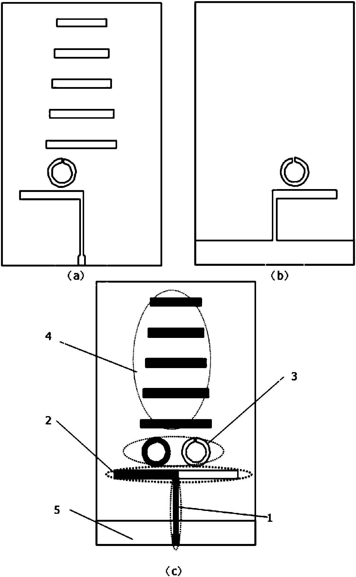
[0025] Such as figure 1 As shown, the dual-frequency Yagi antenna structure diagram with a split resonator ring, in the figure, 1-transmission line, 2-dipole, 3-split resonator ring, 4-director group, 5-reflector. figure 1 Among them, (a) is the upper surface (front) of the dielectric plate, including a transmission line, a dipole, a split resonant ring and a director group located on the upper surface of the di...


PUM


Abstract

The invention discloses a dual-frequency high-gain yagi antenna comprising a dielectric plate, transmission lines, a dipole, open-loop resonators, a reflector and directors. Two resonators are respectively printed on two surfaces of the dielectric plate. One arm of the dipole is connected with the transmission line on the upper surface of the dielectric plate and the other arm is connected with the reflector by the transmission line at the lower surface of the dielectric plate. The five directors with the lengths reduced successively are arranged on the upper surface of the dielectric plate. On the basis of the planar printed yagi antenna, the open-loop resonators are introduced; and because of the resonant effect of the dipole and the open-loop resonators, the dual-frequency work of the antenna is realized. The dipole not only is an excitation source but also is a reflector and the resonators not only serves as excitation sources but also serves as directors. While the dual-frequencyoperation is carried out, the high gain effect within the two operating frequency bands is realized. Moreover, the antenna having a simple structure is easy to process with low cost.

Description

technical field [0001] The invention relates to the field of dual-band Yagi antennas, in particular to a dual-frequency high-gain Yagi antenna with a split resonant ring and a high-directivity radiation field. Background technique [0002] Antenna, as the eyes of wireless communication, is a direct factor affecting communication quality and efficiency. At the present stage, there are mainly two types of micro-repeater donor antennas that should be used in mobile phone communication systems such as GSM, CDMA, 3G, and 4G: one is a logarithmic periodic antenna, which has a wider operating frequency band but a lower gain. And the communication distance is short. The other is the Yagi Uda antenna named by Yagi Hideji and Uda Taro, or Yagi antenna. The Yagi antenna includes an active vibrator, a passive reflector and several side-by-side passive directors. The Yagi antenna is end-fired The antenna has a higher gain than the ordinary single dipole antenna, but the high gain of th...

Claims


Application Information

Patent Timeline
IPC IPC(8): H01Q1/38H01Q5/10H01Q5/20H01Q19/10H01Q19/30
CPCH01Q1/38H01Q5/10H01Q5/20H01Q19/10H01Q19/30
Inventor 谭洪舟陈智聪曾淼旺安德烈·安德烈尼克路崇曾衍瀚
Owner SYSU CMU SHUNDE INT JOINT RES INST
Learn More