Eureka AIR delivers breakthrough ideas for toughest innovation challenges, trusted by R&D personnel around the world.

Fiber perimeter sensing and positioning system and method for determining position of intrusion perturbation point

A technology of sensing positioning and optical fiber perimeter, which is used in the direction of using optical devices to transmit sensing components, alarms by breaking/disturbing straightened ropes/wires, and converting sensor outputs, which can solve the problem of failure to achieve accurate Alarms etc.

Pending Publication Date: 2018-02-06
武汉孚晟科技有限公司
View PDF0 Cites 2 Cited by
  • Summary
  • Abstract
  • Description
  • Claims
  • Application Information

AI Technical Summary

Problems solved by technology

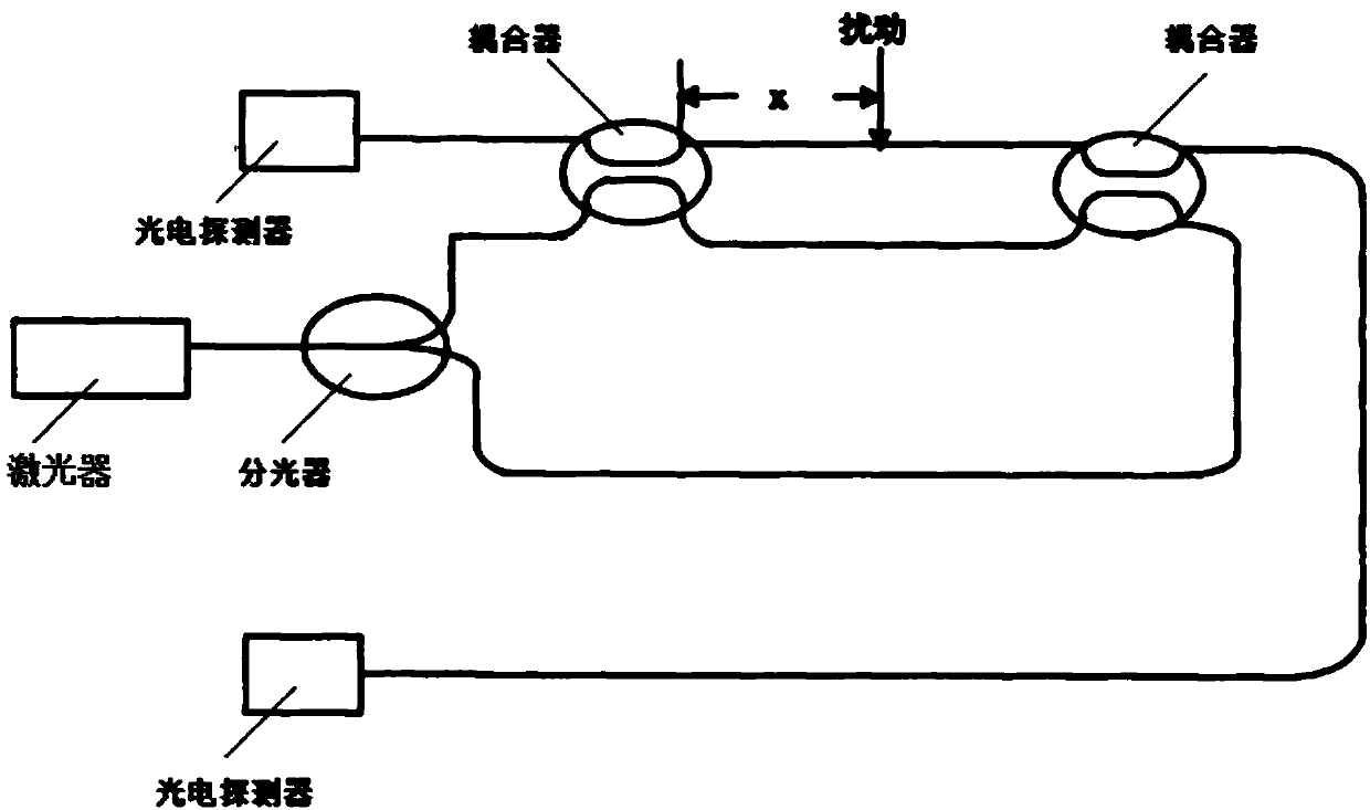
[0004] Existing perimeter sensing and positioning systems based on M-Z interferometers all use the interference arm of the M-Z interferometer as the transmission fiber (such as figure 1 shown), and one of the interference arms is used as the sensing arm, and the other interference arm is used as the reference arm. When the line is laid, the two interference arms of the M-Z interferometer are usually relatively close to each other. When vibration occurs somewhere on the transmission fiber line When , it is possible to make the phase delays of the sensing arm and the reference arm the same, so that no disturbance interference occurs, and precise alarming of faults cannot be achieved

Method used


Image

  • Fiber perimeter sensing and positioning system and method for determining position of intrusion perturbation point
  • Fiber perimeter sensing and positioning system and method for determining position of intrusion perturbation point
  • Fiber perimeter sensing and positioning system and method for determining position of intrusion perturbation point

Examples


Embodiment Construction

[0046] In order to make the technical means, creative features, goals and effects achieved by the present invention easy to understand, the following will further explain how the present invention is implemented in conjunction with the accompanying drawings and specific implementation methods.

[0047] Such as figure 2 As shown, a kind of optical fiber perimeter sensing positioning system provided by the present invention comprises ASE light source 1, and the first blue / red band filter 2 connected with ASE light source 1, and the first blue / red band filter 2 The first M-Z interferometer A connected, and the second M-Z interferometer B connected with the first blue / red band filter 2, and the first photodetector 10 and the second M-Z interferometer A connected Blue / red band filter 7, and the second photodetector 11 that is connected with the second M-Z interferometer B and red / blue band filter 8, and the first operational amplifier 12 that is connected with the first photodetec...


PUM


Abstract

The invention discloses a fiber perimeter sensing and positioning system and a method for determining the position of an intrusion disturbance point. According to the fiber perimeter sensing and positioning system, blue / red-band filters are used for dividing broadband light outputted by an ASE light source into blue band and red band parts with basically equal powers; the divided light enters twoM-Z interferometers respectively; light outputted by the two M-Z interferometers passes through the corresponding blue / red-band filter or the red / blue-band filter and then the processed light is transmitted in a transmission fiber clockwise and counterclockwise respectively; and during the transmission process, scattered light is transmitted to the respective M-Z interferometers by rayleigh scattering to form interference signal and the system carries out identification based on the formed interference signal and determines whether an intrusion event occurs at a fiber path. In addition, the method for determining the position of an intrusion disturbance point that is based on the fiber perimeter sensing and positioning system is used for detecting phenomena like intrusion, vibration and natural destruction on a transmission fiber link and is capable of localizing the position with occurrence of an intrusion event at the fiber path rapidly and accurately.

Description

technical field [0001] The invention relates to the field of optical fiber sensing, in particular to an optical fiber perimeter sensing positioning system and a method for judging the position of an intrusion disturbance point. Background technique [0002] Optical fibers can not only be used to transmit signals, but can also be used as sensors. When external interference affects the optical fiber, some characteristics of the optical fiber transmission light will change. We can know whether the optical fiber is affected by the external environment by monitoring the changes in the characteristics of the light (attenuation, phase, wavelength, polarization, mode field distribution and propagation time). interference. [0003] With the development of society, the safe operation of infrastructure such as schools, factories, financial institutions, airports, military bases, and oil pipelines is related to the vital interests of everyone. Security facilities must be automated to i...

Claims


Application Information

Patent Timeline
IPC IPC(8): G01D5/353G08B13/12
CPCG08B13/124G01D5/35329
Inventor 马延峰王新陈妍周昊
Owner 武汉孚晟科技有限公司
Why Eureka
Eureka Blog
Learn More