
Novel environmental protection device

An environmental protection device, a new technology, applied in the direction of metal processing, etc., can solve the problems of inability to adjust, reduce the efficiency of PVC pipe cutting, and cannot meet the needs of use, and achieve a fixed and stable effect

Inactive Publication Date: 2018-02-06
QUZHOU YANHANG MACHINERY TECH CO LTD
View PDF0 Cites 0 Cited by
  • Summary
  • Abstract
  • Description
  • Claims
  • Application Information

AI Technical Summary

Problems solved by technology

[0002] PVC pipes are popular because of their light weight, corrosion resistance, pressure resistance, and high strength. Due to the different use positions of PVC pipes and the different needs of customers, they usually need to be cut into different lengths. However, in the existing technology, Since the PVC pipe is cylindrical, and there are many types of PVC pipes, and each model has a variety of different diameters, when cutting PVC pipes, the general clamping device can only clamp PVC pipes of the same diameter, and cannot It can be adjusted to meet the needs of clamping various types of PVC pipes with different diameters at the same time. Therefore, this reduces the efficiency of PVC pipe cutting, and the general clamping device cannot meet the existing use requirements.

Method used


Image

  • Novel environmental protection device
  • Novel environmental protection device
  • Novel environmental protection device

Examples


Embodiment Construction

[0020] The preferred embodiments of the present invention will be described in detail below in conjunction with the accompanying drawings, so that the advantages and features of the present invention can be more easily understood by those skilled in the art, so as to define the protection scope of the present invention more clearly.

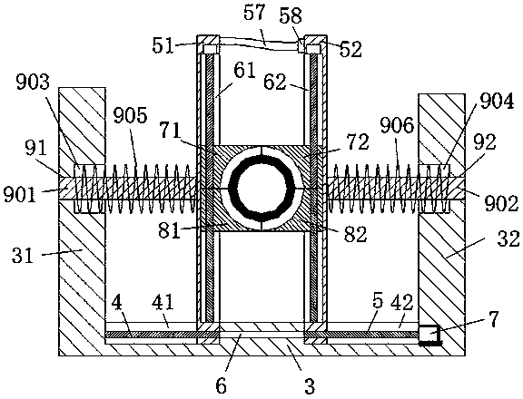
[0021] refer to Figure 1-4A kind of novel environmental protection device shown, comprises seat board 3, and described seat board 3 top left and right ends are mutually provided with left shelf board 31 and right shelf board 32, and described left shelf board 31 and right shelf board 32 respectively A left lead-in hole 91 and a right lead-in hole 92 are arranged opposite to each other, and the inner ends of the left frame plate 31 and the right frame plate 32 are respectively provided with a left sink connected to the left lead-in hole 91 and the right lead-in hole 92. The entrance hole 903 and the right sinking hole 904, the top of the seat pla...


PUM


Abstract

The invention discloses a novel environmental protection device, which comprises a seat plate. A left frame plate and a right frame plate are arranged opposite to each other at the left and right ends of the top of the seat plate. Lead-in holes, the inner ends of the left frame plate and the right frame plate are respectively provided with a left sink hole and a right sink hole connected with the left lead hole and the right lead hole, and the top of the seat plate is located on the left frame plate and the right frame plate The inner side ends of the first left slide groove and the first right slide groove are respectively arranged opposite to each other, and the left slide frame which can slide left and right is respectively arranged opposite to each other in the first left slide groove and the first right slide groove and the right sliding frame, the inner ends of the left sliding frame and the right sliding frame are respectively provided with a second left sliding groove and a second right sliding groove. The device of the present invention has simple structure, low production cost, and can clamp Firmly fix PVC pipes of different diameters, and it is convenient and fast to remove and clamp the PVC pipes, which increases the efficiency of subsequent cutting and processing of PVC pipes. The operation is simple and convenient, and the overall structure is safe, reliable and reasonable in operation, suitable for popularization and use.

Description

technical field [0001] The invention relates to the technical field of environmental protection, in particular to a novel environmental protection device. Background technique [0002] PVC pipe is very popular because of its light weight, corrosion resistance, pressure resistance and high strength. Due to the different use positions of PVC pipes and the different needs of customers, it usually needs to be cut into different lengths. However, in the existing technology, Since the PVC pipe is cylindrical, and there are many types of PVC pipes, and each model has a variety of different diameters, when the PVC pipe is cut, the general clamping device can only clamp the PVC pipe of the same diameter, and cannot It can be adjusted to meet the requirement of clamping various types of PVC pipes with different diameters at the same time. Therefore, this reduces the efficiency of PVC pipe cutting, and the general clamping device cannot meet the existing use requirements. Contents of...

Claims


Application Information

Patent Timeline
Patent Type & Authority Applications(China)
IPC IPC(8): B26D7/02B26D7/22
CPCB26D7/02B26D7/22B26D2007/013
Inventor 张淑丽
Owner QUZHOU YANHANG MACHINERY TECH CO LTD
Learn More