
Propulsion-type lawn mowing device

A mowing device and propulsive technology, which is applied in the direction of cutters, harvesters, agricultural machinery and implements, etc., can solve the problems of limited application range, different pruning sizes, laborious use, etc., and achieve wide application range, neat and beautiful pruning , the effect of reliable connection

Inactive Publication Date: 2018-02-06
CHENGDU XINNENG INTERNET TECH CO LTD
View PDF6 Cites 0 Cited by
  • Summary
  • Abstract
  • Description
  • Claims
  • Application Information

AI Technical Summary

Problems solved by technology

[0004] In view of the above deficiencies, the purpose of the present invention is to provide a push-type lawn mowing device, which mainly solves the problems of limited application range, laborious use, and different trimming sizes in the prior art.

Method used


Image

  • Propulsion-type lawn mowing device
  • Propulsion-type lawn mowing device
  • Propulsion-type lawn mowing device

Examples


Embodiment 1

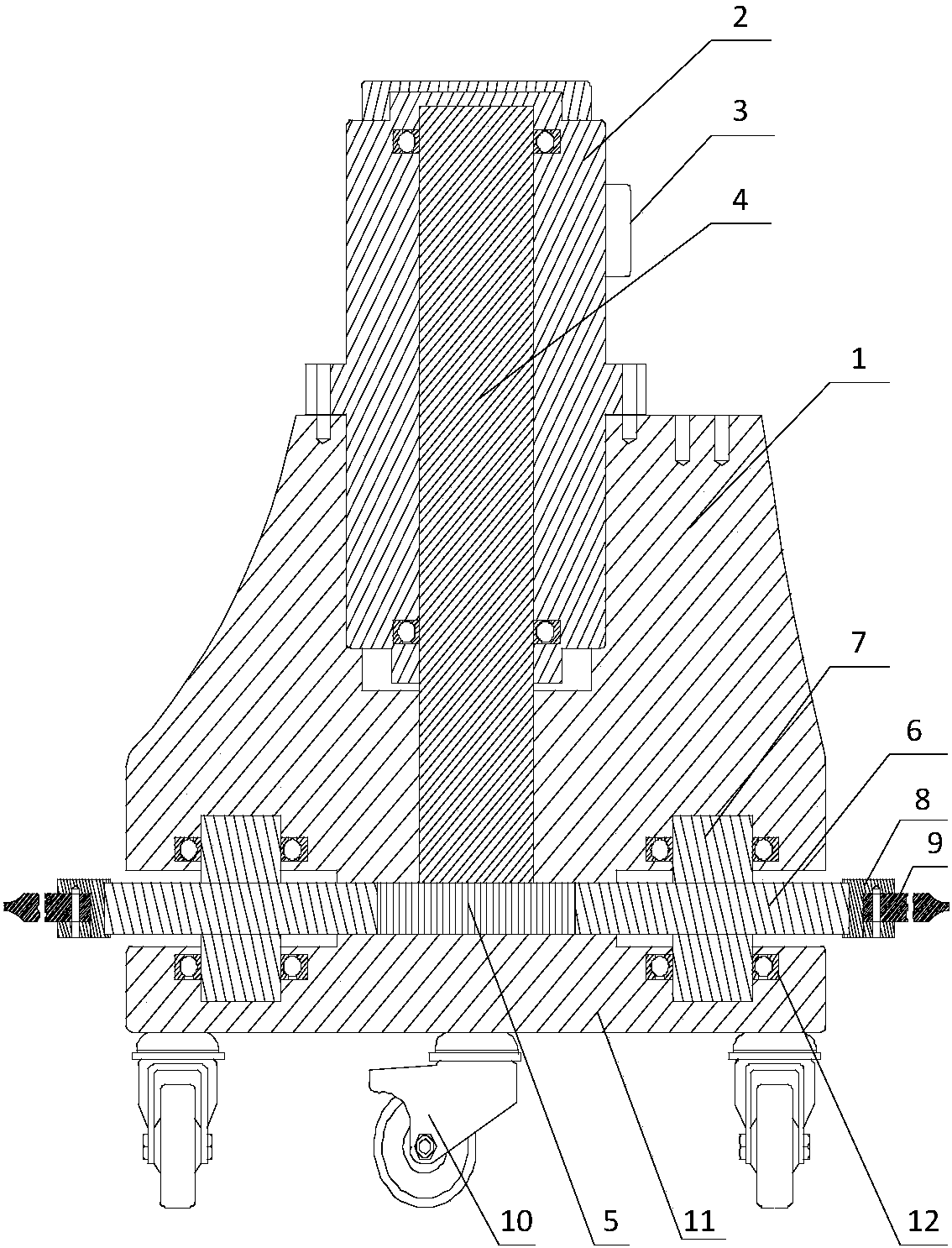
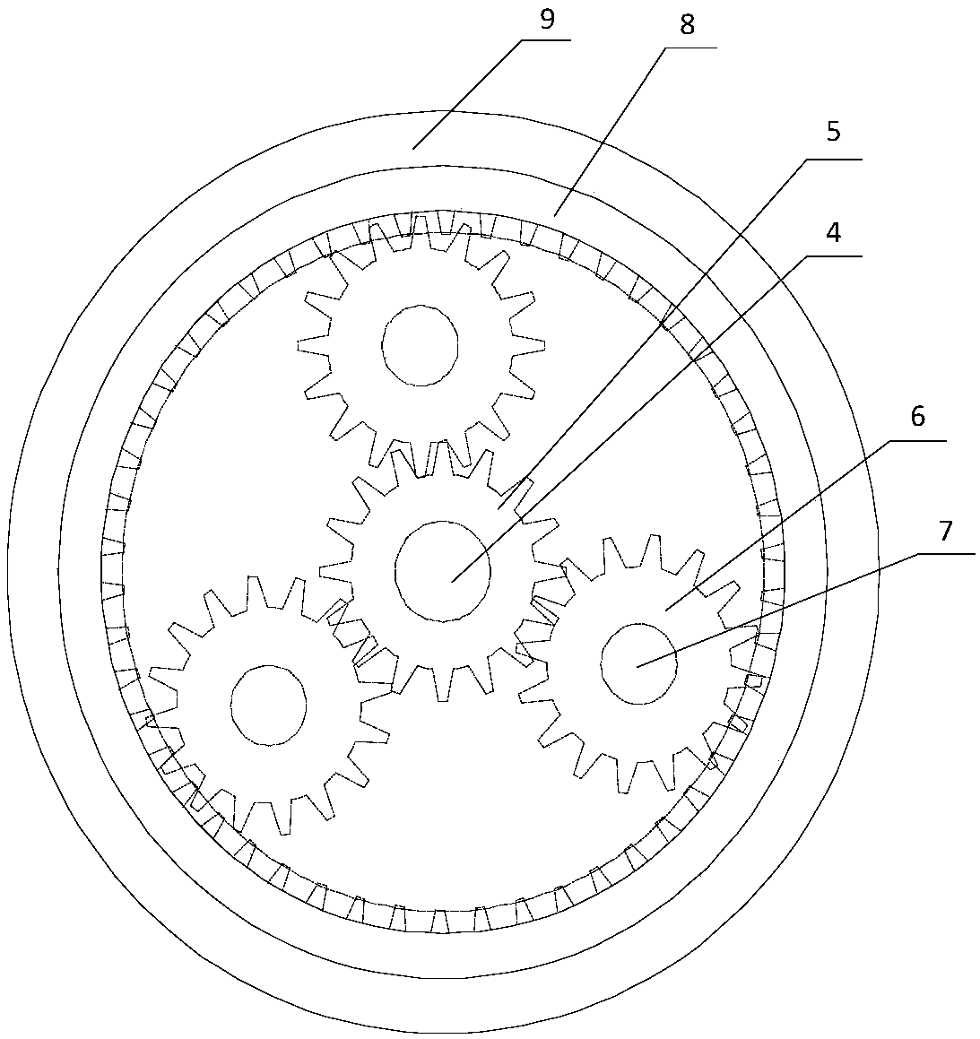
[0024] Such as Figure 1 to Figure 3 As shown, a push-type lawn mowing device includes a cutting motor 2, a junction box 3 arranged on the edge of the outer wall of the cutting motor 2 housing, a motor shaft 4 arranged in the cutting motor 2, connected with the cutting motor 2 housing The cutting propulsion base 1, the motor gear 5 arranged at one end of the motor shaft 4, the lower bottom plate 11 arranged at the bottom of the cutting propulsion base 1, the three drive gears 6 meshing with the motor gear 5, coaxial with the drive gear 6 Center, integrally formed and the upper and lower ends respectively penetrate the support bearing 7 in the cutting propulsion base 1 and the lower bottom plate 11, sleeved on the end of the support bearing 7, the rolling bearing 12 for providing rolling friction, meshed in the inner part of the drive gear 6 The toothed disc 8, the cutting blade 9 fixed on the inner toothed disc 8 and in the shape of a ring, and the four universal wheels 10 arr...

Embodiment 2

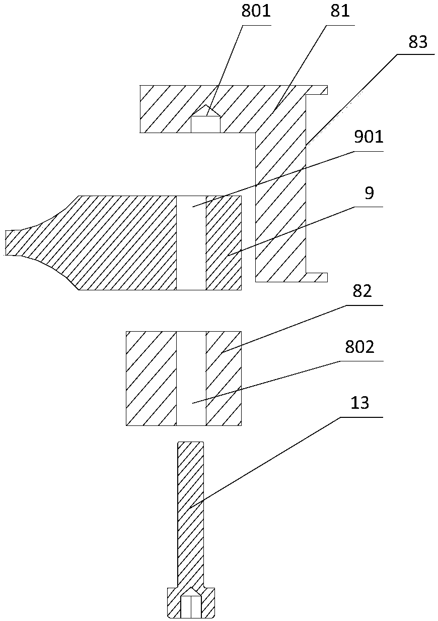
[0027] Such as Figure 4 As shown, other parts of its mowing device are all the same, only the difference between the inner toothed disc 8 and the cutting blade 9, wherein the inner toothed disc 8 includes an upper inner toothed disc (81) and an extrusion plate 82, and the upper inner toothed disc 81 The bottom circle is provided with a blind hole 801 for fixing the cutting blade 9, and the extruding plate 82 is L-shaped, and the first through hole 802 matching the blind hole 801 is arranged on the extruding plate 82, and the inner hexagonal bolt 13 is used. The cutting blade 9 is fastened and pressed between the upper inner gear plate 81 and the pressing plate 82, and the cutting blade 9 is in the shape of a ring.


PUM


Abstract

The invention discloses a propulsion-type lawn mowing device. The lawn mowing device mainly solves the problems that in the prior art, the application range is limited, existing lawn mowing devices are laborious to use, and the trimming sizesare different. The mowing device comprises a cutting motor, a cutting propulsion base connected with a cutting motor shell, a motor gear arranged at one end portion of a motor rotating shaft, a lower base plate arranged at the bottom of the cutting propulsion base, three driving gears meshed with the motor gear, a support bearing, a rolling bearing, an inner tooth disc meshed with the driving gears, an annular cutting blade fixed to the inner tooth disc, and four universal wheels; the support bearing is integrally and coaxially formed with the drivinggears, the upper and lower end portions of the support bearing penetrate through the cutting propulsion base and the lower base plate respectively, the end portion of the support bearing is sleeved with the rolling bearing, the rolling bearing is used for providing rolling friction, and the four universal wheels are arranged at the bottom of the lower base plate and used for forwarding movement. The propulsion-type lawn mowing device has the advantages of being simple in structure, convenient to install and replace, wide in application range, capable of saving labor during operation, neat andbeautiful in trimming shape and the like.

Description

technical field [0001] The invention relates to the technical field of agricultural machinery, in particular to a push-type lawn mowing device. Background technique [0002] With the steady advancement of urban construction, the environmental green ring has become an important part of the municipal work. Lawns planted in parks, street green belts and other areas need to be trimmed regularly. Lawn mowers for lawn trimming are generally divided into trolley type and backpack type. The lawn mower mainly consists of cutter head, engine, walking wheel, walking mechanism, blade, handrail and control part. Its working efficiency can reach 8 to 10 times that of manual weeding, with low seedling injury rate and high seedling removal and cleaning rate. , due to its heavy weight, it is only suitable for wide and flat areas, and it is inconvenient to move and trim the area next to the road (with steps). The knapsack mower consists of cutter head, engine, armrest and control parts. Alth...

Claims


Application Information

Patent Timeline
Patent Type & Authority Applications(China)
IPC IPC(8): A01D34/68
CPCA01D34/68
Inventor 庄慧敏
Owner CHENGDU XINNENG INTERNET TECH CO LTD
Learn More