Structure used for motor rotor cooling

A technology of motor rotor and rotor coil, which is applied in cooling/ventilation device, magnetic circuit shape/style/structure, electric components, etc. efficiency, improve heat dissipation efficiency, and reduce costs

Pending Publication Date: 2018-02-02
HEFEI JUYI POWER SYST CO LTD
View PDF5 Cites 7 Cited by
  • Summary
  • Abstract
  • Description
  • Claims
  • Application Information

AI Technical Summary

Problems solved by technology

The heat dissipation environment is becoming more and more severe, causing the temperature of the motor to rise, resulting in the life and reliability of the product
The rotor is severely tested in this process. Excessive temperature rise will cause an increase in the number of magnets, and it will also increase the cost of magnets
At present, the commonly used cooling method is motor water cooling, which cannot cool and protect the rotor.
[0003] For the heat dissipation of the rotor, the water-cooling system cannot dissipate heat from the rotor, and the risk can only be avoided by protecting the rotor through prediction and selecting high-temperature-resistant magnetic steel, resulting in complicated control and increased costs; the oil cooling system is optimized through the oil circuit , can achieve the purpose of rotor heat dissipation, but the structure is complicated, and a separate oil circulation system needs to be added, which increases the cost and affects the application and promotion

Method used


Image

  • Structure used for motor rotor cooling
  • Structure used for motor rotor cooling
  • Structure used for motor rotor cooling

Examples


Embodiment Construction

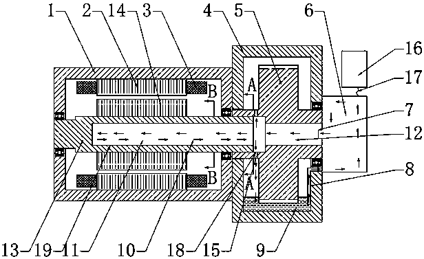
[0023] Such as figure 1 As shown, the motor part in the figure includes a motor housing 1, a motor stator 2, a stator winding 3, a motor rotor 14, and a rotating shaft 13; figure 1 It also includes the transmission casing 4, the transmission gear 5 of the transmission part, the liquid oil 9 at the bottom of the transmission casing 4, and the oil pump 6 and the oil pump control unit 16 outside the transmission.

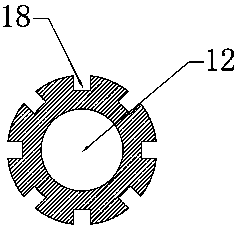
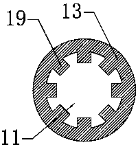
[0024] The transmission gear 5 and the center of the rotating shaft 13 are respectively provided with a gear hollow cavity 12 and a shaft hollow cavity 11 connected to each other, and one end of the transmission gear connected to the rotating shaft is provided with a return hole 15, and the other end of the gear hollow cavity of the transmission gear is connected to Through the oil outlet 7 of the oil pump 6, the oil pump 6 is controlled and connected by the oil pump control signal 17 of the oil pump control unit 16, and the oil 9 inside the transmission is connected t...


PUM


Abstract

The invention discloses a structure used for motor rotor cooling. The structure comprises a transmission gear which is fixedly connected with one end of the rotating shaft of a rotor and arranged in atransmission shell. The center of the transmission gear and the rotating shaft is provided with a gear hollow cavity and a shaft hollow cavity which are mutually connected. One end, which is connected with the rotating shaft, of the transmission gear is provided with a back flow hole. The other end of the gear hollow cavity of the transmission gear is connected with an oil pump. The oil pump andthe back flow hole are connected with the liquid oil in the transmission. According to the scheme, the motor rotor is cooled on the basis of minimizing cost increasing; the simple oil cooling system is additionally arranged in the water cooling system for cooling and heat radiation of the rotor especially so that the temperature of the motor rotor can be reduced and the effect of protecting the rotor and magnetic steel can be realized; and the present new energy automobiles use the water cooling system, and a set of simple oil cooling system is additionally arranged so that the cost can be saved, the reliability of the product can be guaranteed and the application prospect is huge.

Description

technical field [0001] The invention relates to motor rotor cooling technology, in particular to a structure for cooling the motor rotor. Background technique [0002] The main function of the motor is to convert electrical energy into mechanical energy, thereby generating torque, as a driving source for various mechanical equipment. During the operation of the motor, loss will occur. At present, the motor of new energy vehicles is gradually tending to high power density and high speed, and the problem of motor temperature rise is gradually becoming prominent. The heat dissipation environment is becoming more and more severe, causing the temperature of the motor to rise, resulting in the life and reliability of the product. The rotor is severely tested during this process. Excessive temperature rise will cause an increase in the number of magnets, and at the same time increase the cost of the magnets. At present, the commonly used cooling method is motor water cooling, whi...

Claims


Application Information

Patent Timeline
Patent Type & Authority Applications(China)
IPC IPC(8): H02K1/32H02K9/19
CPCH02K1/32H02K9/19Y02T10/64
Inventor 刘蕾田旭
Owner HEFEI JUYI POWER SYST CO LTD
Why Eureka
Try Eureka