Target positioning method and system under large-tilt remote observation environment

A target positioning and environmental technology, applied in the field of surveying and mapping science, can solve the problems of limited target positioning accuracy, large initial value error of target points, and ineffective observation of laser ranging

Active Publication Date: 2018-02-02
WUHAN UNIV
View PDF6 Cites 11 Cited by
  • Summary
  • Abstract
  • Description
  • Claims
  • Application Information

AI Technical Summary

Problems solved by technology

Generally, laser ranging can only achieve the positioning of a single target. If there is a laser missing target during the tracking process (such as tracking a building), the laser ranging will not be effectively observed, the initial value of the target point has a large error, and the laser device Low power leads to insufficient observation information within the effective observation range. The target positioning accuracy obtained by using the laser ranging equation is limited. In addition, only using laser ranging for target positioning cannot take advantage of video image multi-target recognition and tracking.
Therefore, no matter whether using video images for GPS or POS-assisted beam adjustment and using the forward intersection method for target positioning, or directly using laser ranging equations for target positioning, both methods have insufficient information extraction, and they have mutual differences. Complementarity, target positioning accuracy has a lot of room for improvement

Method used


Image

  • Target positioning method and system under large-tilt remote observation environment
  • Target positioning method and system under large-tilt remote observation environment
  • Target positioning method and system under large-tilt remote observation environment

Examples


Embodiment Construction

[0087] The specific technical solutions of the present invention will be described below according to the drawings and embodiments.

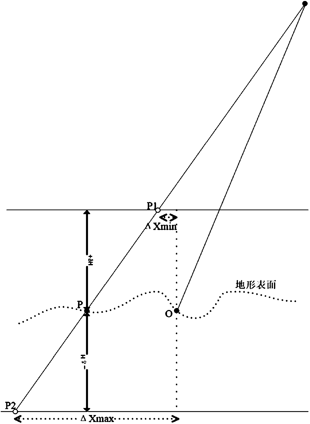
[0088] The invention provides a target positioning method in a large-tilt remote observation environment. This method is suitable for flying platforms that provide video images and laser ranging devices, where video images are used to display targets, and laser devices are used to measure the distance from targets to flying platforms. Acquisition of image exterior orientation elements and target positioning under certain conditions. The study found that when the target is observed at a large tilt and long distance, it is difficult to achieve high-precision positioning of the target by using only video images according to the traditional GPS-assisted beam adjustment method. The reason is that there is no ground control information and no high-precision attitude determination equipment. Under certain conditions, the accuracy of GPS-assisted beam ...


PUM


Abstract

The invention provides a target positioning method and system under a large-tilt remote observation environment. The target positioning method is characterized in that video images and laser ranging information are integrated to achieve target positioning. The target positioning method comprises the steps of carrying out data preparation, performing target coarse positioning by using the laser ranging information to serve as a constraint condition, determining a coordinate extrapolation tolerance range of a ground feature point, and modifying initial coordinate values of the ground feature point; performing GPS-aided bundle block adjustment with virtual control point constraints by taking a target point as a virtual control point; and performing nonlinear iteration solving for forward intersection target positioning by taking the target coarse positioning result as an initial value and taking the acquired image position and attitude as known conditions, and repeating the above steps toimprove the target positioning accuracy. The target positioning method effectively integrates advantages of an optical sensor and a laser device on information acquisition, not only can meet the requirement of laser single-target positioning, but also can meet the requirement of optical video image multi-target positioning, and improves the target positioning accuracy to the great extent.

Description

technical field [0001] The invention belongs to the field of surveying and mapping science and technology, and relates to a target positioning technology in a large-tilt remote observation environment. Background technique [0002] Using video images to track and lock the target of interest is one of the current research hotspots. For UAV images, the position and attitude sensors on the platform (such as global positioning system GPS and inertial measurement unit IMU sensor) can be used to assist the automatic matching technology of the observed target for target positioning. In the field of surveying and mapping science, in order to obtain high-precision target positions, beam adjustment is usually used to correct the position and attitude of the observation platform, so that the forward intersection method is used to obtain the target position. [0003] In some reconnaissance platforms, they are generally equipped with video equipment, inertial integrated navigation devic...

Claims


Application Information

Patent Timeline
IPC IPC(8): G01S17/66G01C11/36
CPCG01C11/00G01S17/66G01C11/36
Inventor 张永军谢勋伟李彦胜
Owner WUHAN UNIV
Why Eureka
Try Eureka