
A high-performance solid ablative pulsed plasma electric propulsion device

A technology of pulsed plasma and solid propellant, which is applied in the direction of using plasma, thrust reverser, machine/engine, etc., can solve the problems of unstable thrust performance, weakened electromagnetic acceleration performance, long discharge time, etc., so as to improve the thrust effect. And work efficiency, improve the effect of electrothermal acceleration, the effect of large discharge ablation area

Active Publication Date: 2019-06-18
BEIJING RES INST OF PRECISE MECHATRONICS CONTROLS
View PDF5 Cites 2 Cited by
  • Summary
  • Abstract
  • Description
  • Claims
  • Application Information

AI Technical Summary

Problems solved by technology

However, this method does not consider the problem of energy distribution, and the designed external circuit has a large loss, especially the external inductance reaches the level of micro-H, resulting in long discharge time, low current peak value, and little ablation quality, which cannot effectively improve the performance of the thruster. performance
[0005] Chinese patents CN101260873B and CN102297105A respectively propose a "pulsed plasma thruster with ceramic nozzle electrodes" and "a pulsed plasma thruster with ceramic nozzles on the side wall". However, the ceramic nozzle will weaken the electromagnetic acceleration performance to a certain extent.
However, the direction of the electric field designed in this patent restricts the ejection of the plasma, which reduces the acceleration effect of charged particles; at the same time, after multiple ignitions, the ablation of the propellant will cause the geometric size of the discharge chamber to change, and the thrust performance is not good. Stablize

Method used

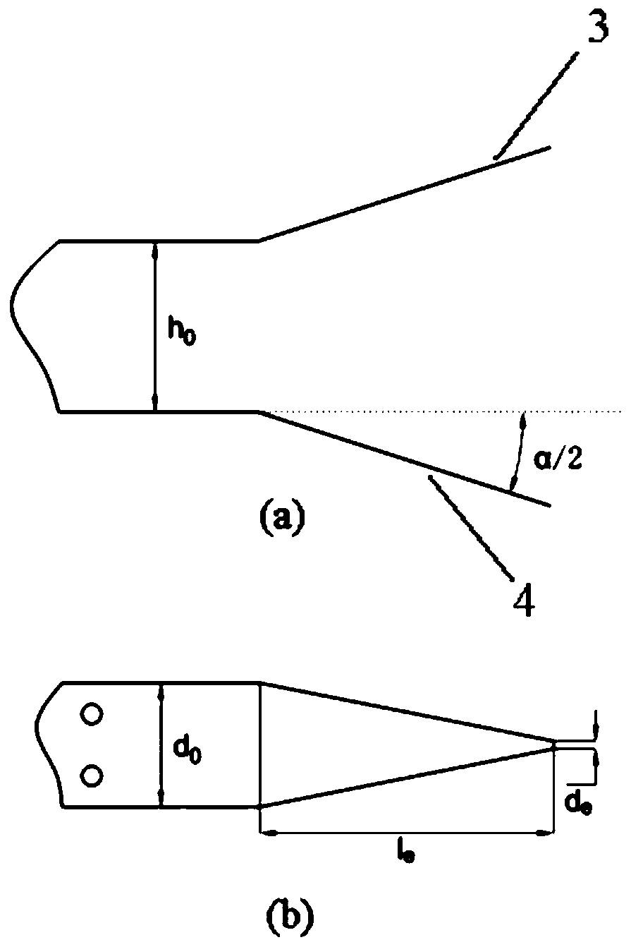
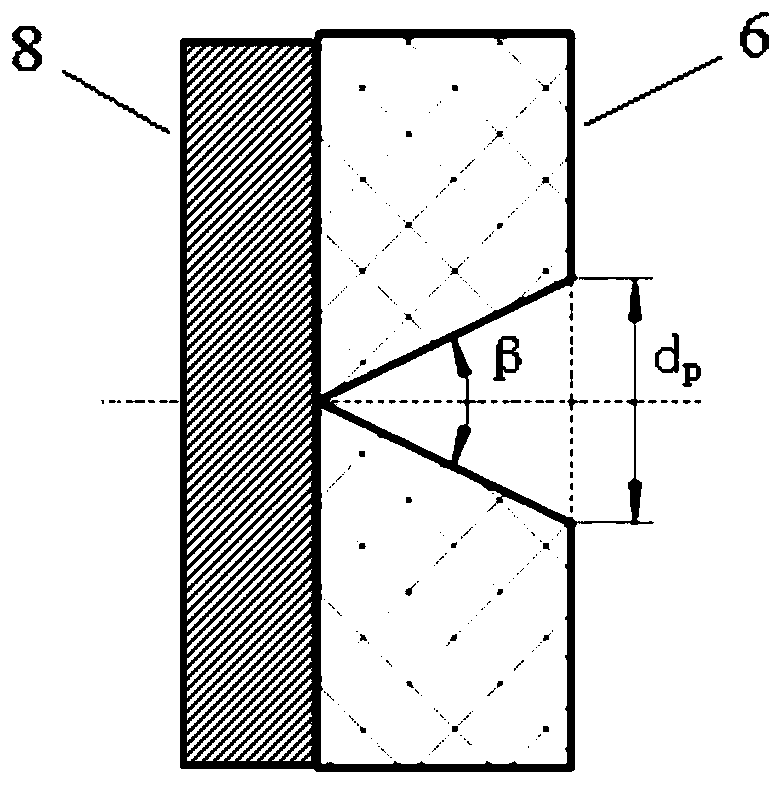

Image

  • A high-performance solid ablative pulsed plasma electric propulsion device
  • A high-performance solid ablative pulsed plasma electric propulsion device
  • A high-performance solid ablative pulsed plasma electric propulsion device

Examples


Embodiment Construction

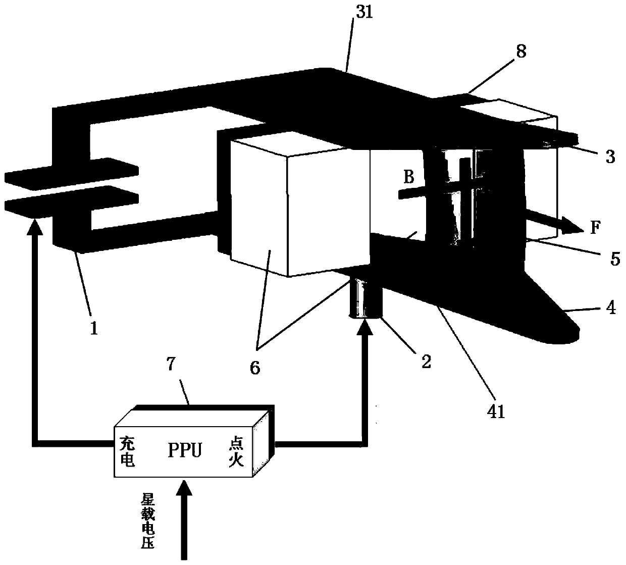
[0025] The essence of the low performance of the solid ablative pulsed plasma electric propulsion device lies in the low utilization rate of the propellant. In order to solve the above technical problems, the present invention proposes a new type of electric propulsion device, which can effectively improve the electrothermal and electromagnetic acceleration impulse, thrust, total impulse and overall thrust efficiency of the plasma formed by propellant ablation, and finally improve Performance of electric propulsion units.

[0026] Such as figure 1 As shown, the device of the present invention includes an energy storage capacitor 1 , a spark plug 2 , an anode 3 , a cathode 4 , a propellant block 6 , a power processing unit PPU 7 , an insulating material 8 , an anode conductive plate 31 and a cathode conductive plate 41 . The anode 3 is connected to the anode of the energy storage capacitor 1 through the anode conductive plate 31, the cathode 4 is connected to the cathode of th...


PUM


Abstract

A high-performance solid ablation type pulse plasma electric propulsion device comprises an energy-storing capacitor, a spark plug, an anode, a cathode, a propellant block, a power processing unit PPU, insulating materials, an anode current-conducting plate and a cathode current-conducting plate. The anode is connected with the anode of the energy-storing capacitor through the anode current-conducting plate, and the cathode is connected with the cathode of the energy-storing capacitor through the cathode current-conducting plate. The propellant block is arranged between the anode current-conducting plate and the cathode current-conducting plate. The insulating materials are also connected between the anode current-conducting plate and the cathode current-conducting plate and attached to the non-discharge side face of the solid propellant block. A V-shaped groove is formed in the center of the solid propellant block. The spark plug is mounted on the lower surface of the cathode current-conducting plate, and the spark plug corresponds to the V-shaped groove of the solid propellant block in position. An ignition port of the power processing unit PPU is connected with the spark plug, and a discharge port of the power processing unit PPU is connected with the cathode of the energy-storing capacitor. The high-performance solid ablation type pulse plasma electric propulsion device issimple in structure, large in discharge ablation area, good in electro-thermal and electromagnetic acceleration effect and capable of effectively improving the thrust performance.

Description

technical field [0001] The invention relates to a space electric propulsion system, in particular to a solid ablation pulse plasma electric propulsion device for in-orbit propulsion of a miniature space vehicle, which belongs to the technical field of energy and power systems. Background technique [0002] Every breakthrough in the aerospace industry depends on the development of propulsion technology, and new space activities will inevitably put forward new requirements for propulsion technology. In recent years, small space vehicles such as small satellites, micro-nano satellites, and cube satellites have been used in low-cost space experiments, communications, earth observation and Navigation and positioning and other fields have broad application prospects. However, due to the limitation of overall power and mass, the on-orbit propulsion technology of micro-space vehicles requires power devices to have the characteristics of low power consumption, light weight, small si...

Claims


Application Information

Patent Timeline
Patent Type & Authority Patents(China)
IPC IPC(8): F03H1/00
CPCF03H1/0006F03H1/0012F03H1/0093
Inventor 杨磊郑再平黄玉平杨斌赵絮皮利萍
Owner BEIJING RES INST OF PRECISE MECHATRONICS CONTROLS
Learn More