
Guiding device of varnished wire

A technology of guiding device and enameled wire, which is applied in the directions of transportation and packaging, delivery of filamentous materials, thin material processing, etc. It can solve the problems of guide wheel groove damage and inefficient maintenance methods, so as to reduce the difficulty of installation and simplify installation and replacement Steps, Guided Flexible Effects

Pending Publication Date: 2018-02-02
湖州华上电工科技股份有限公司
View PDF11 Cites 2 Cited by
  • Summary
  • Abstract
  • Description
  • Claims
  • Application Information

AI Technical Summary

Problems solved by technology

[0002] At present, in the production process of enameled wire, metal wires, such as copper wires, need to be coated with lubricating oil after being enamelled and dried. The enameled wire guide part adopts guide wheels, however, ordinary guide wheels or guide wheel grooves are linearly integrated, that is, the guide wheel grooves are grooves arranged at regular intervals on a cylindrical bar, so that once some guide wheels are encountered If the slots are damaged, the entire row of guide wheel slots needs to be disassembled
This maintenance method is really inefficient, and often the entire row of guide wheel slots will be removed due to the damage of one guide wheel slot, and the paint coating machine will be suspended.

Method used


Image

  • Guiding device of varnished wire
  • Guiding device of varnished wire
  • Guiding device of varnished wire

Examples


Embodiment 1

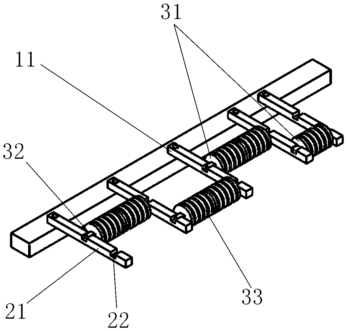
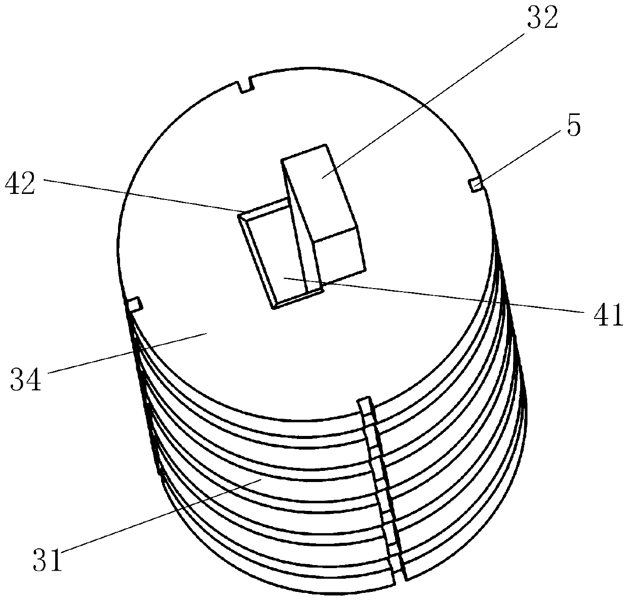
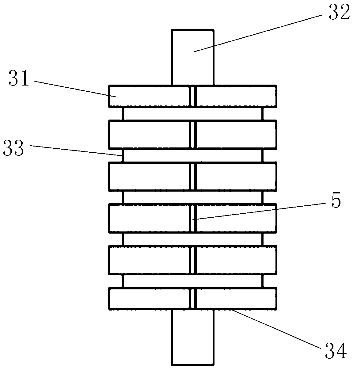
[0030] Example 1, such as figure 1 Shown is an overall schematic diagram of a guide device for enameled wire, a guide device for enameled wire, which includes a fixed rod for fixed connection on the enamelling machine, rack wheel rods 11 arranged at intervals in the length direction of the fixed rod and The guide wheel for guiding the enameled wire, the rack wheel rod 11 includes a fixed part and a rod body 21 for fixed connection with the fixed rod, and the rod body 21 is a straight bar extending horizontally from the upper surface of the fixed rod to the side of the fixed rod The rod has a wheel groove 22 for placing guide wheels on the side of the shaft 21 away from the fixed rod. The wheel groove 22 is a groove extending downward from the upper surface of the shaft 21 and arranged at intervals. The guide wheel includes a wheel body 31 and The wheel bar 32 is used to be embedded in the wheel groove 22. The wheel body 31 is a cylindrical block, and there are guide grooves 33...


PUM


Abstract

The invention discloses a guiding device of a varnished wire and relates to the field of varnished wire production. A conventional single-row guide groove guiding manner is changed into a structure formed by combining a plurality of guiding wheels which are arranged in an alternate manner and provided with guiding grooves, the situation that the whole row of guiding grooves need to be dismounted and maintained when a single guiding groove is damaged is avoided, the installing and replacing steps of the guiding wheels are simplified, and guiding of the varnished wire is more flexible. The guiding device comprises a fixing rod which is used for being fixedly connected to an enamelling machine, wheel erecting rods which are arrayed in the length direction of the fixing rod at intervals and the guiding wheels which are used for guiding the varnished wire. Each wheel erecting rod comprises a fixedly-connecting part which is used for being fixedly connected with the fixing rod and a rod body, wherein the side, far away from the fixing rod, of the rod body is provided with wheel grooves used for placing the corresponding guiding wheels. Each guiding wheel comprises a wheel body and a wheel rod which is used for being embedded into the corresponding wheel grooves. The side surface of each wheel body is provided with the guiding grooves which are used for guiding the varnished wire andare arrayed at intervals.

Description

technical field [0001] The invention relates to the field of enameled wire production, in particular to a guiding device for enameled wires. Background technique [0002] At present, in the production process of enameled wire, metal wires, such as copper wires, need to be coated with lubricating oil after being enamelled and dried. The enameled wire guide part adopts guide wheels, however, ordinary guide wheels or guide wheel grooves are linearly integrated, that is, the guide wheel grooves are grooves arranged at regular intervals on a cylindrical bar, so that once some guide wheels are encountered If the slots are damaged, the entire row of guide wheel slots needs to be disassembled. This kind of maintenance method is not efficient, often because of the damage of a guide wheel groove, the whole row of guide wheel grooves will be removed and the paint coating machine will be suspended. Contents of the invention [0003] The purpose of the present invention is to provide...

Claims


Application Information

Patent Timeline
IPC IPC(8): B65H57/14B65H57/16B65H57/04
CPCB65H57/04B65H57/14B65H57/16B65H2701/34
Inventor 沈林华
Owner 湖州华上电工科技股份有限公司
Learn More