
Projection device, projection method, projection module, electronic device, and program

A projection device and projection technology, applied in the direction of using projection device image reproducer, TV, color TV, etc., can solve the problem of image quality degradation and achieve the effect of improving image quality

Active Publication Date: 2018-01-26
SONY GRP CORP
View PDF5 Cites 9 Cited by
  • Summary
  • Abstract
  • Description
  • Claims
  • Application Information

AI Technical Summary

Problems solved by technology

[0008] As a result, the image quality of the image projected on the screen has degraded due to interference between point lights

Method used


Image

  • Projection device, projection method, projection module, electronic device, and program
  • Projection device, projection method, projection module, electronic device, and program
  • Projection device, projection method, projection module, electronic device, and program

Examples


Embodiment Construction

[0072]

[0073] figure 1 A configuration example of a projection system 1 to which the present technology is applied is shown.

[0074] The projection system 1 includes a projector 11 , a main controller 12 , a distance measuring unit 13 and a screen 14 .

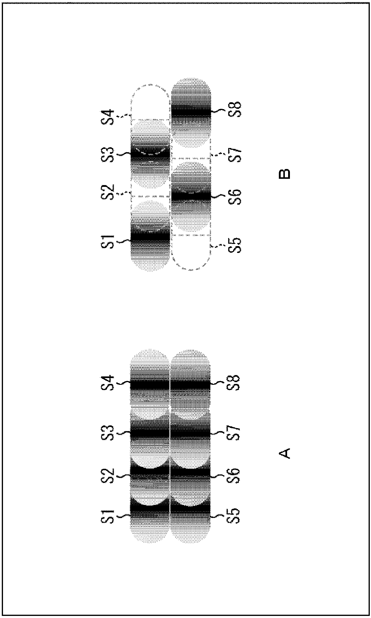
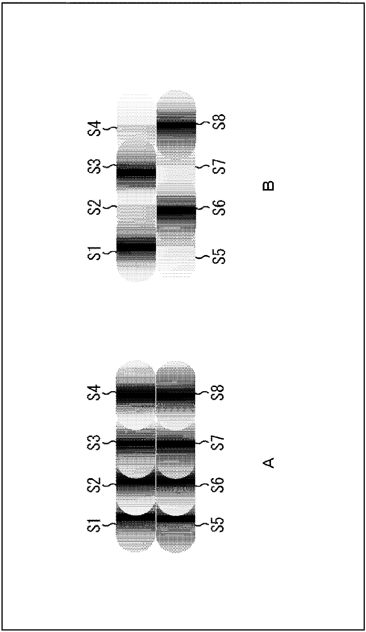
[0075] Incidentally, the projection system 1 suppresses interference between point lights each of which is point-like light projected as a pixel at each position on the screen 14, and improves the image quality of a projected image projected on the screen 14 .

[0076] That is, for example, projector 11 controls emission of laser beams based on the distance to screen 14 , the position where spot lights are projected on screen 14 , etc., to suppress interference between spot lights on screen 14 .

[0077] Incidentally, it is known that on the screen 14, interference between spot lights is more likely to occur as the distance to the screen 14 is shorter and the position on the screen 14 where the spot lights are projected...


PUM


Abstract

The invention relates to a projection device, a projection method, a projection module, an electronic device, and a program. The present invention relates to a projection device and a projection method that make it possible to correct optical axis deviation, a projection module, an electronic device, and a program. Test emission of a laser beam serving as a light source is performed in a projection device and the position of the optical axis thereof is determined by a light amount ratio detected by a photodetector (PD) that is a two-dimensional flat surface perpendicular to the optical axis and that is divided into a plurality of regions. Optical axis deviation is determined on the basis of information relating to the RGB optical axis, a correction coefficient is calculated for correctingpixel position deviation on a projection image that is projected on a screen, the pixel position at which projection should occur is corrected by the correction coefficient, and deviation of the RGB optical axis is thereby corrected. The present invention can be applied to a projection device.

Description

technical field [0001] The present invention relates to a projection device, a projection method, a projection module, an electronic device and a program, and more particularly to a projection device, a projection method, a projection module, an electronic device and a program capable of improving the image quality of an image projected by a projector. Background technique [0002] Generally, for example, there is a projector that scans a screen as a target so that laser light reciprocates sinusoidally (for example, see Patent Document 1). [0003] With this projector, a driving mirror for reflecting a laser beam is driven, and the laser beam reflected from the driving mirror is emitted to each position on the screen. [0004] Therefore, point light as point light is projected by emitting a laser beam at each position on the screen. That is, on the screen, an image in which a plurality of point lights each is a pixel is projected. [0005] Incidentally, scanning of the las...

Claims


Application Information

Patent Timeline
Patent Type & Authority Applications(China)
IPC IPC(8): H04N5/74G02B26/10G09G3/02H04N9/31
CPCH04N9/3164G02B26/101G09G3/025H04N9/3129H04N9/3185H04N9/3194G09G2320/029
Inventor 中村仁
Owner SONY GRP CORP
Learn More