
Contact line system

A sliding wire and sliding connection technology, applied in the direction of overhead wires, single contact elements, etc., can solve problems such as limiting flexibility, and achieve the effect of avoiding ignition sparks

Active Publication Date: 2018-01-26
SIEMENS MOBILITY GMBH
View PDF9 Cites 0 Cited by
  • Summary
  • Abstract
  • Description
  • Claims
  • Application Information

AI Technical Summary

Problems solved by technology

During plant expansions, one-time prescribed measures must be strictly observed, which limits flexibility in the selection of technical solutions or in the selection of suppliers

Method used


Image

  • Contact line system
  • Contact line system
  • Contact line system

Examples


Embodiment Construction

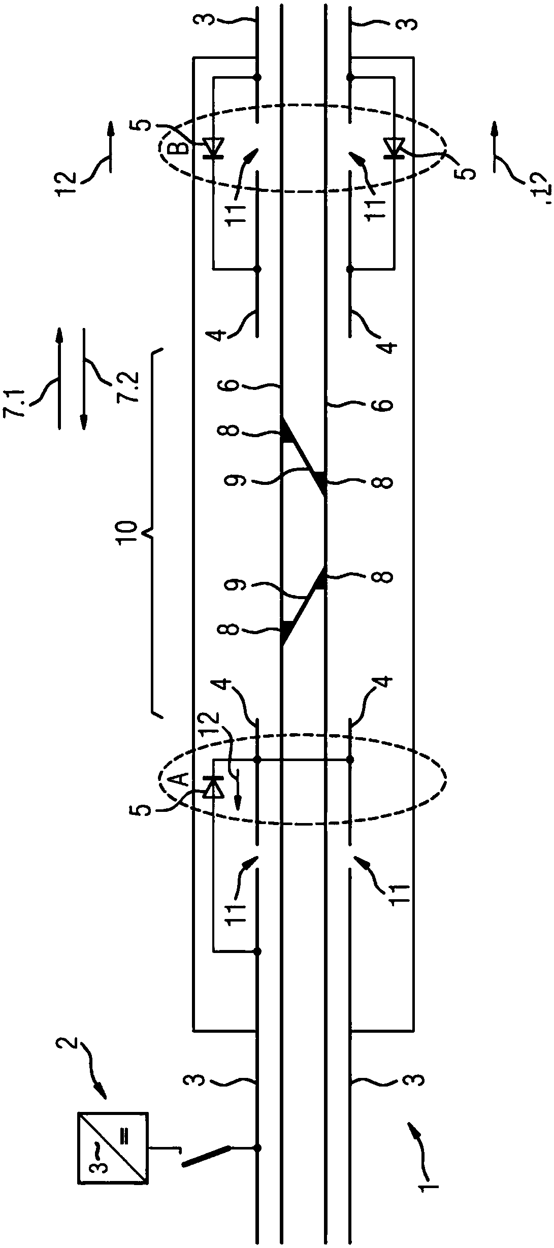
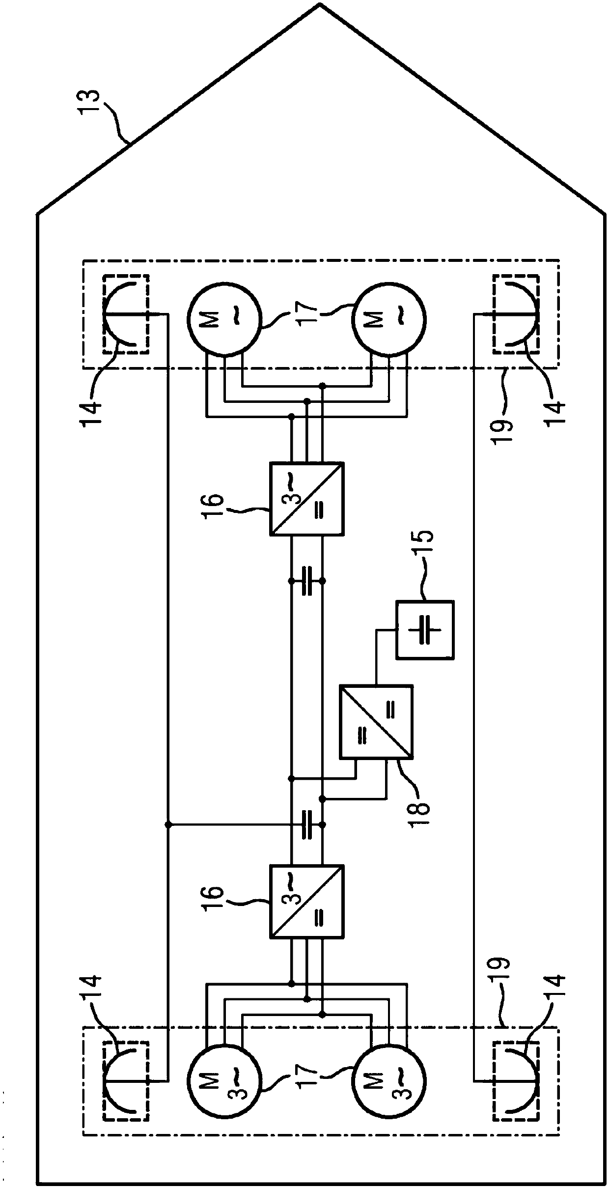
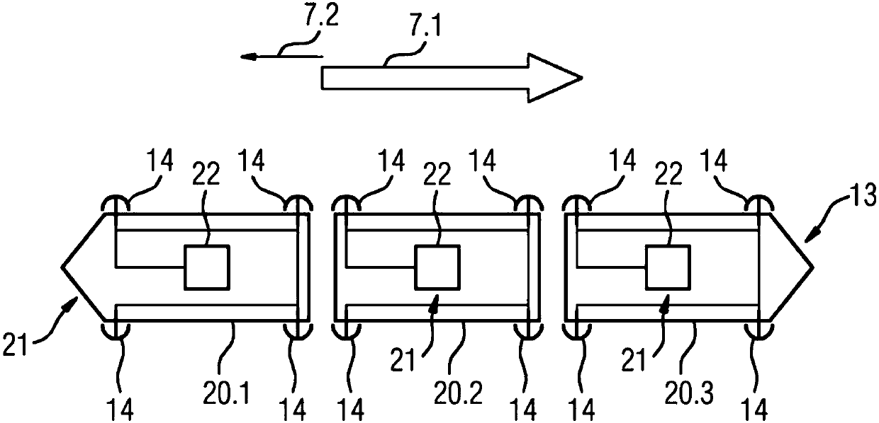
[0021] First, refer to figure 1 with figure 2 The present invention will be described in terms of exemplary embodiments. figure 1 An exemplary embodiment of a conductor line arrangement 1 according to the invention is shown, which has an energy source 2 , a first conductor track section 3 , a second conductor conductor section 4 and an electrical component 5 . The first and second conductor track sections 3 , 4 are designed, for example, as busbars and are arranged, for example, laterally to the track 6 . The two travel routes 6 are each configured, for example, as a track pair. exist figure 1 In this case, two travel lanes arranged parallel to one another are formed, on which the vehicles can travel in each case in two opposite travel directions 7 . In order to change the travel route, a switch 8 and a connecting route 9 are formed for the two travel routes 6 . The first and second conductor track sections 3 , 4 are each arranged laterally of each track 6 as viewed in t...


PUM


Abstract

The invention relates to a contact line system (1) for supplying energy to at least one vehicle (13) moving in a direction (7.1, 7.2) of travel relative to the contact line system (1), said system comprising: at least one first contact line section (3); at least one second contact line section (4) arranged behind the first contact line section (3) in the direction of travel; at least one energy source (2) connected to the first contact line section (3) and to the second contact line section (4); and at least one electrical component (5), which at least restricts current flow in a reverse direction from the second contact line section (4) to the energy source (2) and permits current flow in opposition to the reverse direction.

Description

technical field [0001] The invention relates to a trolley wire arrangement for supplying energy to at least one vehicle moving relative to the trolley wire arrangement in the direction of travel. Background technique [0002] The conductor track arrangement is used, for example, to supply different types of rail vehicles or other vehicles with energy and is designed, for example, as an overhead line or as a busbar, wherein the busbar can be designed as an overhead busbar or also as a bridge in the ground area of ​​a travel route. Side third rail. Power supply systems of this type based on side-guided busbars are known, for example, from subway systems and are generally used for supply voltages up to approximately 1000 volts direct current. However, applications in long-distance traffic, for example on British railways, are also known. Busbar systems, in particular side-guided busbar systems, have the problem that the busbar must be regularly interrupted at branch roads, in...

Claims


Application Information

Patent Timeline
Patent Type & Authority Applications(China)
IPC IPC(8): B60M1/36B60M1/18
CPCB60M1/18B60M1/36
Inventor M.诺亚克
Owner SIEMENS MOBILITY GMBH
Learn More