Overcurrent protection driving circuit and electric vehicle motor controller

An overcurrent protection and drive circuit technology, applied in electrical components, electronic switches, pulse technology, etc., can solve the problems of large drive circuit, cumbersome circuit, complex circuit structure, etc., to achieve sensitive overcurrent protection, simple circuit, volume small effect

Inactive Publication Date: 2018-01-26
佛山中锦微电科技有限公司
View PDF0 Cites 0 Cited by
  • Summary
  • Abstract
  • Description
  • Claims
  • Application Information

AI Technical Summary

Problems solved by technology

[0004] 1. Many power tubes do not have the overcurrent protection function of the power tube. Once the overcurrent is overheated, the power tube is easily damaged
[0005] 2. For some circuits with overcurrent protection function, the current sampling is generally performed by connecting a large current resistor in series with the main circuit of the power device. When the current exceeds the standard, the comparison circuit judges and then cuts off the control signal at the input end of the power tube. This method is indirect Over-current sampling, the sampling signal lags behind the time when the power tube over-current occurs, and the protection action is often started only after severe over-current, resulting in more damage caused by the power tube over-current, which reduces the reliability of the circuit
[0006] 3. The circuit structure described in the above 2 is relatively complex, high in cost, and unsatisfactory in performance
[0007] 4. Some ASICs with overcurrent protection function either have the above-mentioned shortcoming of protection lag, or their cost is relatively high
[0008] 5. Part of the drive circuit with over-current protection function does not have the automatic reset function after over-current protection, which requires the circuit to be restarted and reset or an additional matching oscillator circuit on the circuit to generate a reset pulse for other excitation reset, which makes the circuit more cumbersome
[0009] 6. Part of the drive circuit with over-current protection function is relatively large

Method used


Image

  • Overcurrent protection driving circuit and electric vehicle motor controller
  • Overcurrent protection driving circuit and electric vehicle motor controller
  • Overcurrent protection driving circuit and electric vehicle motor controller

Examples


Embodiment 1

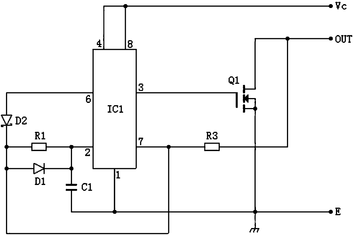
[0026] Such as figure 1 As shown, the structural features of this circuit include time base circuit IC1, timing capacitor C1, first resistor R1, first diode D1, first voltage regulator tube D2 or second resistor R2, third resistor R3, power Tube Q1, the negative pole (1) of the power supply of the time base circuit is grounded, the positive pole (8) of the time base circuit is connected to the positive pole Vc of the power supply, the zero clearing terminal (4) of the time base circuit is connected to the external control signal or the positive pole Vc of the power supply, the time base circuit The output end (3) of the power tube Q1 is connected to the input end of the power transistor, the low trigger end (2) of the time base circuit is connected to one end of the timing capacitor C1, one end of the first resistor R1, and the negative pole of the first diode D1 at the same time, and the timing capacitor The other end of C1 is grounded E, the other end of the first resistor R...

Embodiment 2

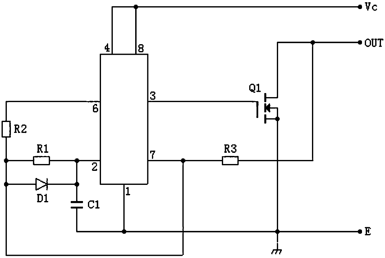
[0034] Such as figure 2 As shown, the time base circuit is a 555 integrated chip. This circuit is the same as the aforementioned figure 2 In comparison, the voltage regulator tube D2 is replaced by the resistor R2, which can also serve as the drain voltage when the power tube is overvoltage passed through R3.

Embodiment 3

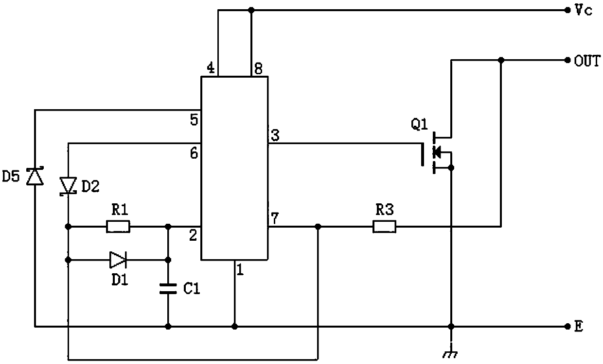
[0036] Such as image 3 As shown, the structural feature of this circuit is that the threshold terminal 5 of the time base circuit is connected to the ground with a Zener diode D5. Since the charging upper limit of the capacitor C1 is adjusted, when the stabilized voltage value of D5 is lower than the high trigger threshold voltage inside the chip , the sensitivity of the overcurrent protection action is improved, and the voltage regulation value of D5 is reduced, and the starting current value of the overcurrent protection will be reduced, and the overcurrent protection is more sensitive. You can also adjust the default time of overcurrent. When there is continuous overcurrent, a pulse of a certain oscillation frequency will appear on the drain of the power tube formed by the charging and discharging of C1. The charging time of C1 is the default time of overcurrent, and its duty cycle is generally designed It can be lower than 1%, which can be determined according to calculat...


PUM


Abstract

The invention provides an overcurrent protection driving circuit comprising a time base circuit IC1, a timing capacitor C1, a first resistor R1, a first diode D1, a first voltage-regulator tube D2, athird resistor R3 and a power tube Q1, wherein a negative electrode of the time base circuit is grounded, the positive electrode and the zero clearing end are connected to the positive electrode of the power supply, an output end is connected with an input end of the power tube, a low triggering end is connected with one end of the timing capacitor, one end of the first resistor and a negative electrode of the first diode at the same time, the other end of the timing capacitor is grounded, the other end of the first resistor and the positive electrode of the first diode are connected with a discharging end of the time base circuit at the same time, the positive electrode of the first voltage-regulator tube or one end of the second resistor is connected with a high triggering end of the time base circuit at the same time, the negative electrode of the first voltage-regulator tube or the other end of the second resistor is connected with the discharging end of the time base circuit, thenegative electrode of the power tube is grounded, and the output end of the power tube is connected with the discharging end via the third resistor; and the overcurrent protection driving circuit hasthe advantages of simple structure, sensitive over current protection, small size, low cost, easy popularization and wide application.

Description

technical field [0001] The invention belongs to the technical field of electronic control, and in particular relates to an overcurrent protection drive circuit and an electric window motor controller. Background technique [0002] Various DC power supply loads need to control their working current through control devices, including DC control and pulse current control, such as the control of electric window motors, etc. This puts forward technical requirements for power tubes in terms of overcurrent resistance. [0003] But the control circuit of prior art has following technical problem: [0004] 1. Many power tubes do not have the overcurrent protection function of the power tube. Once the overcurrent is overheated, the power tube is easily damaged. [0005] 2. For some circuits with overcurrent protection function, the current sampling is generally performed by connecting a large current resistor in series with the main circuit of the power device. When the current excee...

Claims


Application Information

Patent Timeline
IPC IPC(8): H03K17/08
Inventor 杨明
Owner 佛山中锦微电科技有限公司
Why Eureka
Try Eureka