
Wireless charging circuit for lithium battery

A technology of wireless charging and lithium batteries, applied in the direction of battery circuit devices, circuit devices, collectors, etc., can solve the problems of complex circuit structure, low transmission efficiency, poor stability, etc., achieve simple circuit structure, stable operation, and prevent overcharging Effect

Inactive Publication Date: 2018-01-26
安徽灵图壹智能科技有限公司
View PDF0 Cites 7 Cited by
  • Summary
  • Abstract
  • Description
  • Claims
  • Application Information

AI Technical Summary

Problems solved by technology

[0008] The purpose of the present invention is to overcome the technical immaturity problems such as low transmission efficiency, poor stability, low safety, and complex circuit structure in the wireless charging of lithium batteries existing in the above-mentioned prior art, and to provide a wireless charging circuit for lithium batteries

Method used


Image

  • Wireless charging circuit for lithium battery
  • Wireless charging circuit for lithium battery
  • Wireless charging circuit for lithium battery

Examples


Embodiment 1

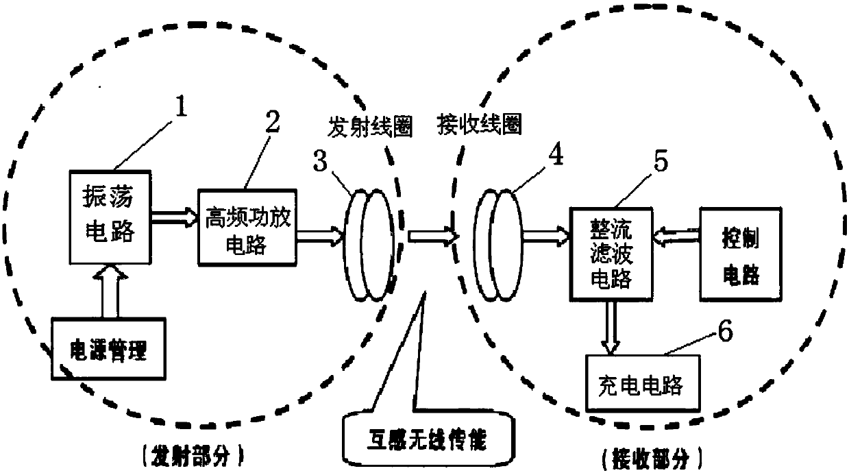
[0023] like figure 2 As shown, the present invention provides a lithium battery wireless charging circuit, including a transmitting part and a receiving part, wherein the transmitting part is composed of an oscillating circuit 1, a high-frequency power amplifier circuit 2 and a transmitting coil 3; the receiving part is composed of a receiving coil 4, rectification and filtering The circuit 5 and the charging circuit 6 are composed; the oscillating circuit 1 is electrically connected with the high-frequency power amplifier circuit 2, and the high-frequency power amplifier circuit 2 is electrically connected with the transmitting coil 3; the receiving coil 4 is electrically connected with the rectifying and filtering circuit 5, and the rectifying and filtering circuit 5 is electrically connected with the The charging circuit 6 is electrically connected; the transmitting coil 3 and the receiving coil 4 are a pair of coupling coils, and they realize the transmission and reception...

Embodiment 2

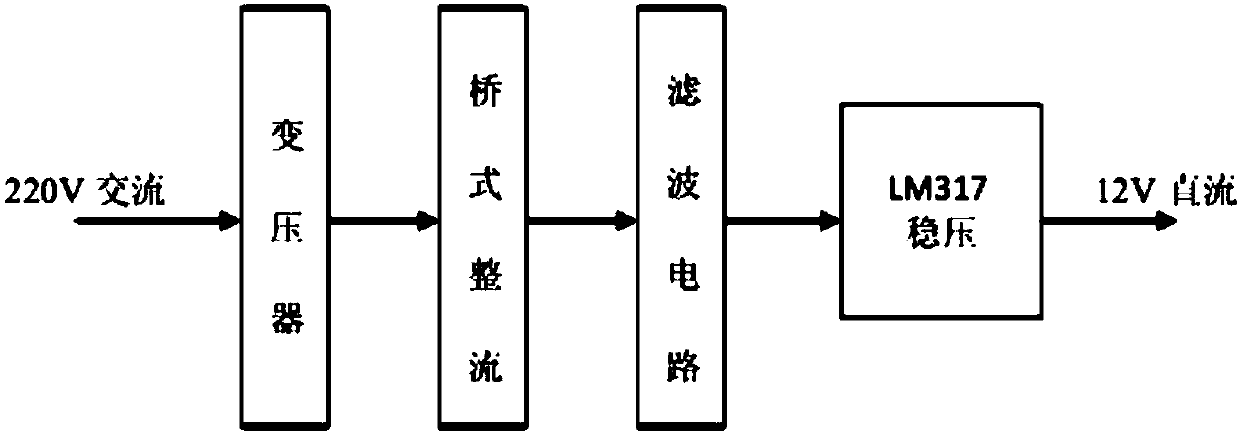
[0026] On the basis of Example 1, such as Figure 4 As shown, this embodiment uses LM317 to form a +12V circuit diagram, and the DC voltage required by the high-frequency power amplifier circuit 2 output by the LM317 voltage regulator chip is 12V DC voltage. The multi-layer air-core coil specifically adopts a patch-type coupling coil, and the shape of the transmitting coil (3) is circular with a diameter of 9 cm; the number of turns is 20; the shape of the receiving coil (4) is circular with a diameter of 9 cm ; The number of turns is 20; The diameter of the copper wire is 0.8mm, the height of the coil is 3cm, the coil winding method is close winding; the coil inductance is L=480uH. like Image 6 As shown, the oscillating circuit 1 adopts the NE555 timing IC chip to form a frequency-adjustable multivibrator circuit. The GND pin of the NE555 timing IC chip is grounded, and the GND pin is 1 pin, which is also connected to the capacitors C1 and C2 respectively. One end, the other...


PUM


Abstract

The invention provides a wireless charging circuit for a lithium battery. The wireless charging circuit comprises a transmitting part and a receiving part, wherein the transmitting part comprises an oscillating circuit (1), a high-frequency power amplifier circuit (2) and a transmitting coil (3); the receiving part comprises a receiving coil (4), a rectifier and filter circuit (5) and a charging circuit (6); the oscillating circuit (1) is electrically connected with the high-frequency power amplifier circuit (2); the high-frequency power amplifier circuit (2) is electrically connected with thetransmitting coil (3); the receiving coil (4) is electrically connected with the rectifier and filter circuit (5); and the rectifier and filter circuit (5) is electrically connected with the chargingcircuit (6). The hazardous conditions, such as overcharge, over-high temperature and over-high current caused in the charging process of the lithium battery are effectively prevented. The whole circuit is simple in structure and stable in working; and the requirement of miniaturization is achieved by a receiving terminal to achieve the practical application level.

Description

technical field [0001] The invention belongs to the technical field of battery wireless charging, and in particular relates to a lithium battery wireless charging circuit. Background technique [0002] When human society develops into the information age, various electronic products have sprung up into people's lives. MP3, MP4, smart phones, tablet PCs and small mobile office equipment, electronic products are moving from simplification to diversification. Every day. However, battery technology has not been able to keep up with the development speed of electronic products. Many smartphone users have no choice but to charge once a day or even more a day. In addition, the lifestyle and consumption concept of modern humans have also undergone earth-shaking changes compared with the past. People are no longer satisfied with electronic products that only have ordinary functions, but hope that electronic products also have a stylish appearance, avant-garde design, and a more co...

Claims


Application Information

Patent Timeline
Patent Type & Authority Applications(China)
IPC IPC(8): H02J7/02H02J50/12
Inventor 不公告发明人
Owner 安徽灵图壹智能科技有限公司
Learn More