
Logic valve for hydraulic excavator

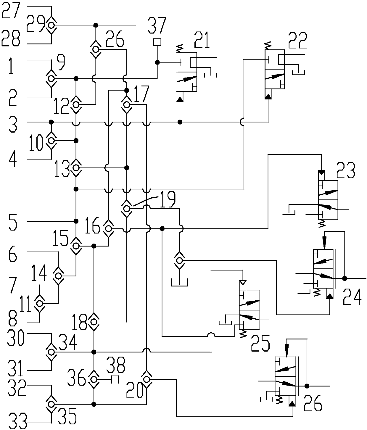
A hydraulic excavator and logic valve technology, applied in the field of logic valves, can solve the problems of high maintenance cost, poor reliability, and difficult maintenance of electronic control units, and achieve the effect of low maintenance cost, high reliability, and simple and clear structure

Pending Publication Date: 2018-01-26
WUXI UCHIDA HYDRAULIC TECH CO LTD
View PDF5 Cites 2 Cited by
  • Summary
  • Abstract
  • Description
  • Claims
  • Application Information

AI Technical Summary

Problems solved by technology

[0005] The technical problem to be solved by the present invention is: the existing electronic control unit is difficult to maintain, has poor reliability and high maintenance cost. The present invention provides a logic valve for hydraulic excavators to solve the above problems

Method used


Image

  • Logic valve for hydraulic excavator
  • Logic valve for hydraulic excavator
  • Logic valve for hydraulic excavator

Examples


Embodiment Construction

[0023] Embodiments of the present invention are described in detail below, examples of which are shown in the drawings, wherein the same or similar reference numerals designate the same or similar elements or elements having the same or similar functions throughout. The embodiments described below by referring to the figures are exemplary only for explaining the present invention and should not be construed as limiting the present invention. On the contrary, the embodiments of the present invention include all changes, modifications and equivalents coming within the spirit and scope of the appended claims.

[0024] In describing the present invention, it should be understood that the terms "center", "longitudinal", "transverse", "length", "width", "thickness", "upper", "lower", "front", " Back", "Left", "Right", "Vertical", "Horizontal", "Top", "Bottom", "Inner", "Outer", "Axial", "Radial", "Circumferential", etc. The indicated orientation or positional relationship is based ...


PUM


Abstract

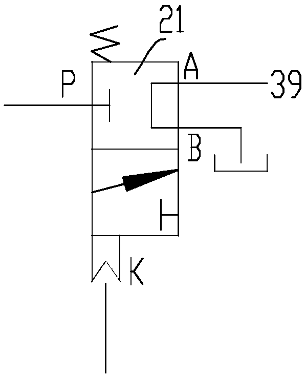
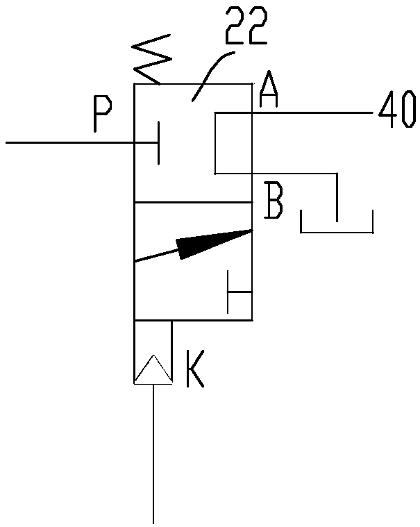
The invention provides a logic valve for a hydraulic excavator. The logic valve comprises a valve body; a left rotary oil pipe, a right rotary oil pipe, a middle arm withdrawing operation oil pipe, amiddle arm raising operation oil pipe, a big arm lifting oil pipe, a big arm falling operation oil pipe, a bucket raising operation oil pipe and a bucket excavating operation oil pipe are arranged onthe valve body in a communicating mode; a rotary shuttle valve, a middle arm operation shuttle valve, a bucket operation shuttle valve, a first parallel-flow shuttle valve, a second parallel-flow shuttle valve, a third parallel-flow shuttle valve, a fourth parallel-flow shuttle valve, a fifth parallel-flow shuttle valve and a rotary brake-release control valve are arranged on the valve body. The logic valve has the advantages that hydraulic elements are mutually connected so that the logic control in the operation process of the hydraulic excavator can be realized, by means of the mode, the hydraulic elements are independent from one another, the structure is simple and clear relative to an electronic control unit, the reliability is high, troubleshooting is convenient when a fault occurs,parts can be replaced in a targeted mode in the maintenance process, and the maintenance cost is low.

Description

technical field [0001] The invention relates to a logic valve, in particular to a logic valve for a hydraulic excavator. Background technique [0002] Hydraulic excavator is a multifunctional machine, widely used in water conservancy projects, transportation, electric power engineering and mining and other mechanical construction, it can reduce heavy physical labor, ensure project quality, speed up construction and improve labor productivity plays a very important role. [0003] In the existing hydraulic excavators, the electronic control unit and the multi-way valve are often used to control the operating state of each action actuator of the hydraulic excavator. The electronic control unit is similar to the driving computer ECU of the car. Stable movement execution plays a vital role. [0004] However, the integration of the electronic control unit is very high. When a small short circuit or interference occurs, the entire control system will easily fail, and the maintena...

Claims


Application Information

Patent Timeline
Patent Type & Authority Applications(China)
IPC IPC(8): E02F3/43E02F9/20
Inventor 郑晓刚徐月萍
Owner WUXI UCHIDA HYDRAULIC TECH CO LTD
Learn More