
An electric vehicle charging and discharging and motor drive integrated device

A motor-driven, electric vehicle technology, applied in the direction of electric vehicle charging technology, electric vehicles, motors, etc., can solve problems such as failure to supply power, limitation of battery life of electric vehicles, failure to provide V2L and V2V functions, etc.

Active Publication Date: 2020-11-17
UNIV OF ELECTRONICS SCI & TECH OF CHINA
View PDF1 Cites 0 Cited by
  • Summary
  • Abstract
  • Description
  • Claims
  • Application Information

AI Technical Summary

Problems solved by technology

[0005] 1. The circuit structure of the driving motor is complex and the cost is high
The motor drive contains a DC / DC converter module, which complicates the structure
At the same time, since the motor drive requires a large power, the DC / DC converter module needs to have a large power output capability, which will increase the corresponding cost;
[0006] 2. Energy recovery without braking
Most electric vehicles today have energy recovery during braking, which can not only improve the cruising range of electric vehicles, but also save energy, so controllers that do not have braking energy recovery will limit the cruising capacity of electric vehicles to a certain extent;
[0007] 3. No interface device for outputting single-phase alternating current
It cannot supply power to other electric vehicles and some mobile appliances, and cannot provide V2L and V2V functions;
[0008] 4. The charging function of the on-board low-voltage battery is not integrated

Method used


Image

  • An electric vehicle charging and discharging and motor drive integrated device
  • An electric vehicle charging and discharging and motor drive integrated device
  • An electric vehicle charging and discharging and motor drive integrated device

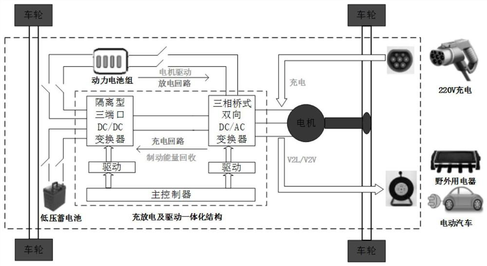
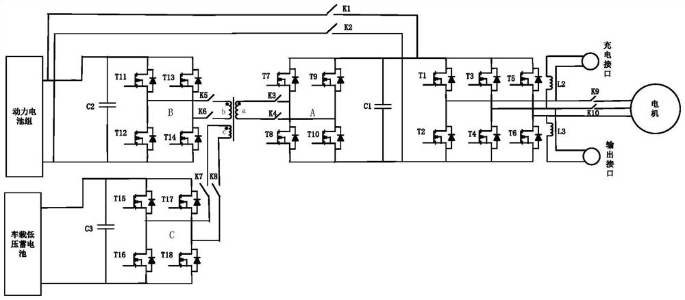
Examples


Embodiment Construction

[0029] The following describes preferred specific embodiments of the present invention in conjunction with the accompanying drawings. It should be noted that identical components appearing in different drawings are assigned the same reference numerals.

[0030]The bidirectional DC / AC converter is a three-phase converter using FS820R08A6P2B IPM module, the corresponding driver and BOOSTER use 1EDI2002AS and 1EBN1001AE chips; the isolated three-port DC / DC converter uses IPP65R150CFDA IGBT, and the corresponding driver uses 2ED020I12FA chip; The controller adopts AURIX TC277 chip, which can detect voltage, current and temperature parameters after expansion, and respond to accelerator pedal input and braking force input.

[0031] A circuit structure of an electric vehicle charging, discharging and motor drive integration device comprising: a charging interface, an output interface, a three-phase motor, a bidirectional DC / AC converter circuit, an isolated three-port DC / DC converter...


PUM


Abstract

The invention discloses an integrated device for charging, discharging and motor driving of an electric vehicle. The device includes a three-phase bridge type bidirectional DC / AC converter, an isolated three-port DC / DC converter, a main controller, and an integrated machine working mode A switching device, a single-phase AC power input interface device, and a single-phase AC power output interface. The present invention reconfigures the topology of the three-phase inverter that drives the motor in the electric vehicle traction system, so as to use it as a single-phase rectifier when charging or as a single-phase inverter when supplying power to the outside, and then form an integrated hardware Circuit configuration. Then in the main controller, according to the integrated control method, the three-phase bridge bidirectional DC / AC converter, the isolated three-port DC / DC converter, the relay switch and the corresponding drive module are controlled and converted to realize the charging and discharging and driving modes Seamless switching, and realize the functions of braking energy recovery, V2V / V2L, and charging of low-voltage batteries on the vehicle. The integrated equipment of the present invention achieves the purposes of optimizing volume, reducing weight, saving cost and improving reliability.

Description

technical field [0001] The invention relates to the field of electric vehicles, in particular to the fields of charging and discharging of electric vehicle power batteries and low-voltage storage batteries and motor driving. Background technique [0002] With the rapid development of the automobile industry, the gradual depletion of oil resources and the increasingly serious environmental pollution, the demand for sustainable energy development has become increasingly strong. Energy conservation and environmental protection have become important issues in the 21st century, and electric vehicle technology has emerged as the times require. Electric vehicles replace oil with electricity to achieve zero emissions. They have the characteristics of simple structure, high energy utilization efficiency, low noise, and low cost of use. It has become the development trend of the global automobile industry. Since the use of motor drive is more convenient to realize the integration of i...

Claims


Application Information

Patent Timeline
Patent Type & Authority Patents(China)
IPC IPC(8): B60L53/22B60L53/24B60L15/00
CPCY02T10/64Y02T10/70Y02T10/7072Y02T10/72Y02T90/14
Inventor 杨峰宋永端李瑞李玉良石亚锋王大松
Owner UNIV OF ELECTRONICS SCI & TECH OF CHINA
Learn More