engine maintenance stand

A maintenance rack and engine technology, applied in the field of aviation machinery, can solve the problems of a single maintenance rack, occupy a large space, and do not have a transfer engine, etc., and achieve the effect of reducing the transfer process, compact structure, and reducing the space occupied.

Active Publication Date: 2021-04-23
CHENGDU CHENGSHE AVIATION TECH
View PDF5 Cites 0 Cited by
  • Summary
  • Abstract
  • Description
  • Claims
  • Application Information

AI Technical Summary

Problems solved by technology

In the process of engine maintenance, the engine is usually fixed on the maintenance rack, and then repaired; the traditional maintenance rack has a single function, takes up a lot of space, and does not have the function of transferring the engine

Method used


Image

  • engine maintenance stand
  • engine maintenance stand
  • engine maintenance stand

Examples


Embodiment Construction

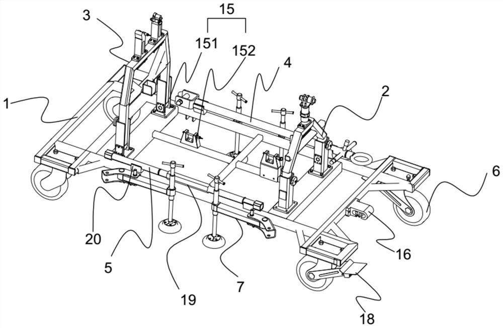
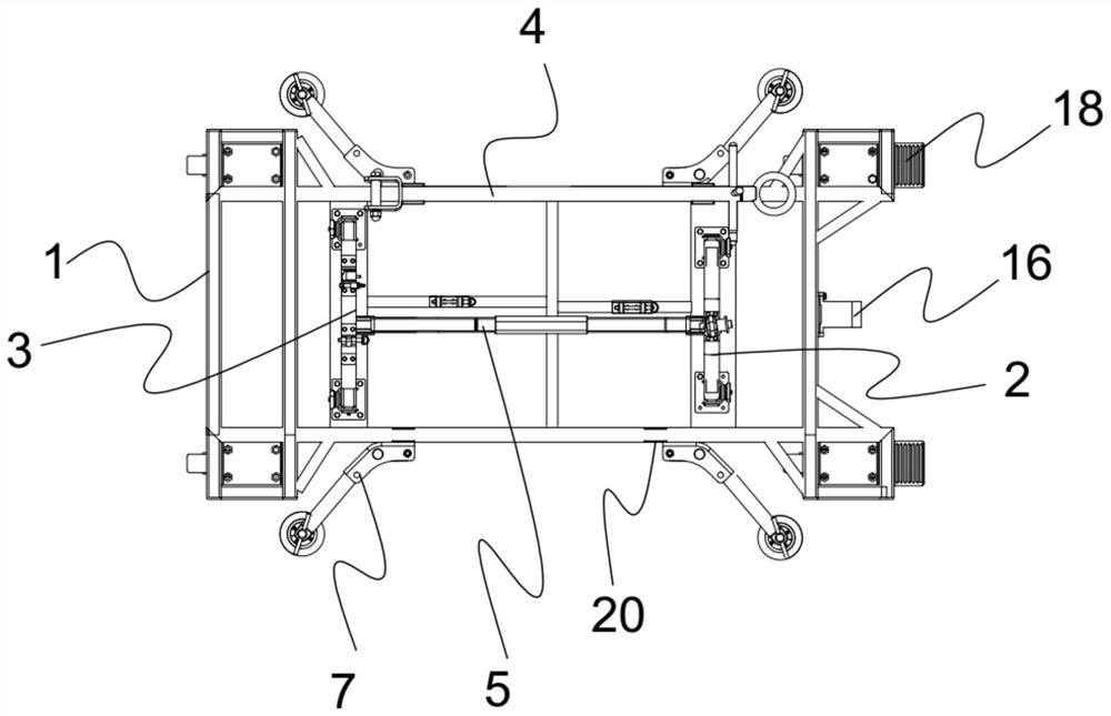
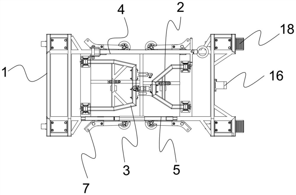
[0019]ReferFigure 1-6The embodiment of the present invention will be specifically described.

[0020]An engine maintenance rack, including a bottom plate 1, a first door frame 2, a second door frame 3, a traction rod 4, and a rod 5, and a roller 6 and a leg assembly 7 are provided on the bottom plate 1. The roller 6 is provided at both ends of the bottom plate 1, the leg assembly 7 disposed on both sides of the bottom plate 1, the leg assembly 7 including the crossbar 71, vertical rod 72, and the length of the vertical rod 72. The rotary handle 73 is hinged on the bottom plate 1, and a threaded sleeve is provided at the other end of the crossbar 71, which is connected to the threaded sleeve. The rotating handle 73 is disposed at the top of the vertical rod 72, and is also provided with a positioning groove 74 for positioning the crossbar 71 on the bottom plate 1, in which the positioning slot 74 and the A positioning hole 75 is provided in a position corresponding to the horizontal bar...


PUM


Abstract

The invention discloses an engine maintenance stand, which comprises a bottom plate, a first door frame, a second door frame, a draw bar and a push rod, rollers and leg assemblies are arranged on the bottom plate, the first door frame and the second door frame Each door frame includes a top beam, a cross beam and a vertical beam. The vertical beam of the first door frame is hinged at one end of the bottom plate, and the vertical beam of the second door frame is hinged at the other end of the bottom plate. The top beam of a door frame is provided with a first installation ear, the top beam of a second door frame is provided with a second installation ear and a third installation ear, and the cross beam of the first door frame and the second door frame The crossbeams of the frame are respectively provided with support grooves for supporting the ejector rods, and a positioning device for fixing the first door frame and the second door frame is arranged on the bottom plate, and the bottom plate is also provided with a hook for the towbar described above. The device of the invention has the advantages of compact structure, small occupied space and convenient use.

Description

Technical field[0001]The present invention belongs to the field of aviation machinery, and in particular to an engine maintenance rack.Background technique[0002]The engine provides power for the flight of the aircraft, and the aircraft maintains normal operation of the engine at time. To keep the engine running reliability, it is necessary to regularly maintain the engine, one is to discover and exclude the failure of the engine, the second is to repair damaged components. In the process of engine repair, the engine is usually fixed on the maintenance frame, and repairs are repaired; the traditional maintenance frame function is single, the space is large, and does not have the function of the transport engine.Inventive content[0003]It is an object of the present invention to solve the shortcomings in the above prior art, providing a simple structure and a convenient engine repair rack.[0004]In order to achieve the above object, the technical solution adopted by the present inventio...

Claims


Application Information

Patent Timeline
Patent Type & Authority Patents(China)
IPC IPC(8): B25H1/06B25H1/08B25H5/00
Inventor 张小双兰永红
Owner CHENGDU CHENGSHE AVIATION TECH
Why Eureka
Try Eureka