Hybrid ship using wind-powered propulsive force as auxiliary

A hybrid and auxiliary technology, applied in wind-propelled ships, engines using a combination of propulsion devices, and ship propulsion. The effect of reducing maintenance work time

Inactive Publication Date: 2018-01-19
森元信吉
View PDF10 Cites 3 Cited by
  • Summary
  • Abstract
  • Description
  • Claims
  • Application Information

AI Technical Summary

Problems solved by technology

That is, as shown in the model diagram of the new Aide Maru in Non-Patent Document 1, since it is necessary to have a partition for the internal combustion engine at the stern, at the same time, it is necessary to bury the sail control mechanism in the center of the ship for other wind propulsion mechanisms. As well as the sail on the deck of the bow and its under deck, not only the additional cost of purchasing the original equipment for sailing, but also the sailing equipment also affects the overall structure of the ship. In combination, the manufacturing cost and development cost inevitable rise
And also produce the following problems, sailing equipment brings the following negative effects
[0008] That is, the method of installing a plurality of sail masts on the deck and placing their supporting structures below the deck not only leads to an increase in manufacturing cost, but also causes the following fundamental problems as a merchant ship: the sails occupying the space on the deck The opening of unloading is restricted by driving equipment, which hinders the loading and unloading operation of unloading, which in turn increases the time and cost of loading and unloading operations
Since the goal is to take the sail as the main part and the engine as the supplement, the area of ​​the sail increases and the burden on its operation increases. Therefore, as disclosed in Patent Document 1, it is conceivable to set the sail as a hard wing and make the mast is characterized by flexibility and focuses on reducing operational burdens, but if evaluated as a merchant vessel, the above problems described in paragraph 0008 also exist
[0011] That is, the following fundamental problem as a merchant ship still occurs: the masts of a plurality of sails are arranged on the board and the supporting structure thereof is arranged below the deck, which not only leads to an increase in manufacturing cost, but also increases the production cost due to the space occupied on the deck. The opening of the unloading is restricted by sailing the equipment, which becomes an obstacle to the loading and unloading operation of unloading, and additionally generates time and cost for loading and unloading
[0012] In addition, the following problems remain the same: not only the cargo loading space installed on the upper part of the ship is occupied by the sailing equipment, but also the cargo capacity in the ship is reduced due to the installation of auxiliary equipment for sailing below the deck. will decrease
If the amount of cargo carried decreases, the fuel cost per unit of loading will increase, so it is conceivable that even if the fuel cost per unit of the hull decreases, the consumption of fuel per unit of loaded cargo and handling costs will increase. The result is that, likewise, even if the consumption of fuel is halved, it will not work for merchant ships
[0013] In addition, since the purpose is a hybrid sailboat in which the sail is the main part and the engine is the supplementary form, if viewed from the stern, there are more than three huge telescopic sailboats with a width of, for example, 20m and a height of 50m when sailing. (Refer to Figure 7 of the full-scale model of Non-Patent Document 2), if viewed from the stern, it will hinder the forward view, so the following problems will also be added: it is different from the Japanese Industrial Standard JIS shown in Non-Patent Document 3 F0420: 2009 (ISO8468: 2007) "Ship and Ocean Technology - Bridge Configuration and Associated Devices - Requirements and Guidelines" are inconsistent
If the bridge is installed at the bow of the ship, a new dead space may be created in the lower part, and even if the space can be used, the use of merchant ships will be limited, or the load during loading and unloading will increase.
[0016] In addition, it is also known that, in the case of adopting a separate living quarters, it is necessary to additionally install the launching equipment of the lifeboat that is usually arranged at the stern at the bow, which leads to further design changes and restrictions on deck design (Non-Patent Document 4 )
[0017] If the bridge is not arranged at the bow, as disclosed in Fig. 1 of Patent Document 2, a plurality of lower-level sails are set on the deck in order to ensure the front view, but the problem of deck occupation is not solved. It is conceivable that there is still the problem of restricted vision when sailing

Method used


Image

  • Hybrid ship using wind-powered propulsive force as auxiliary
  • Hybrid ship using wind-powered propulsive force as auxiliary
  • Hybrid ship using wind-powered propulsive force as auxiliary

Examples


Embodiment Construction

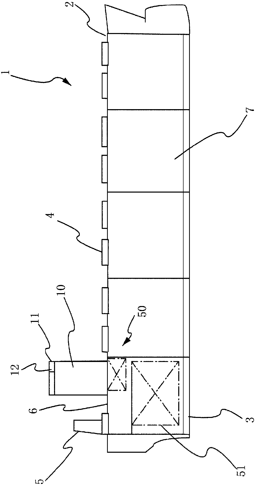
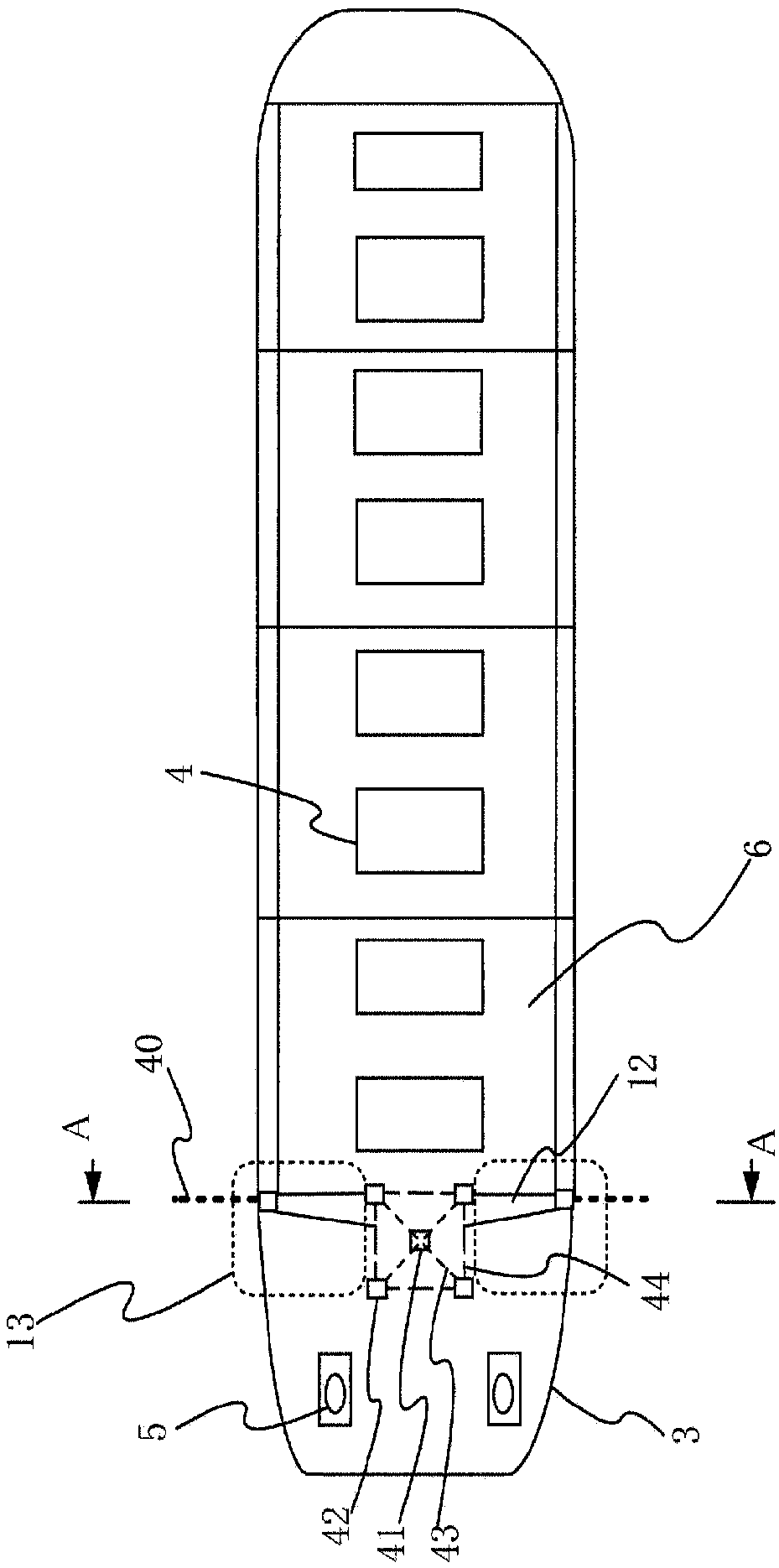
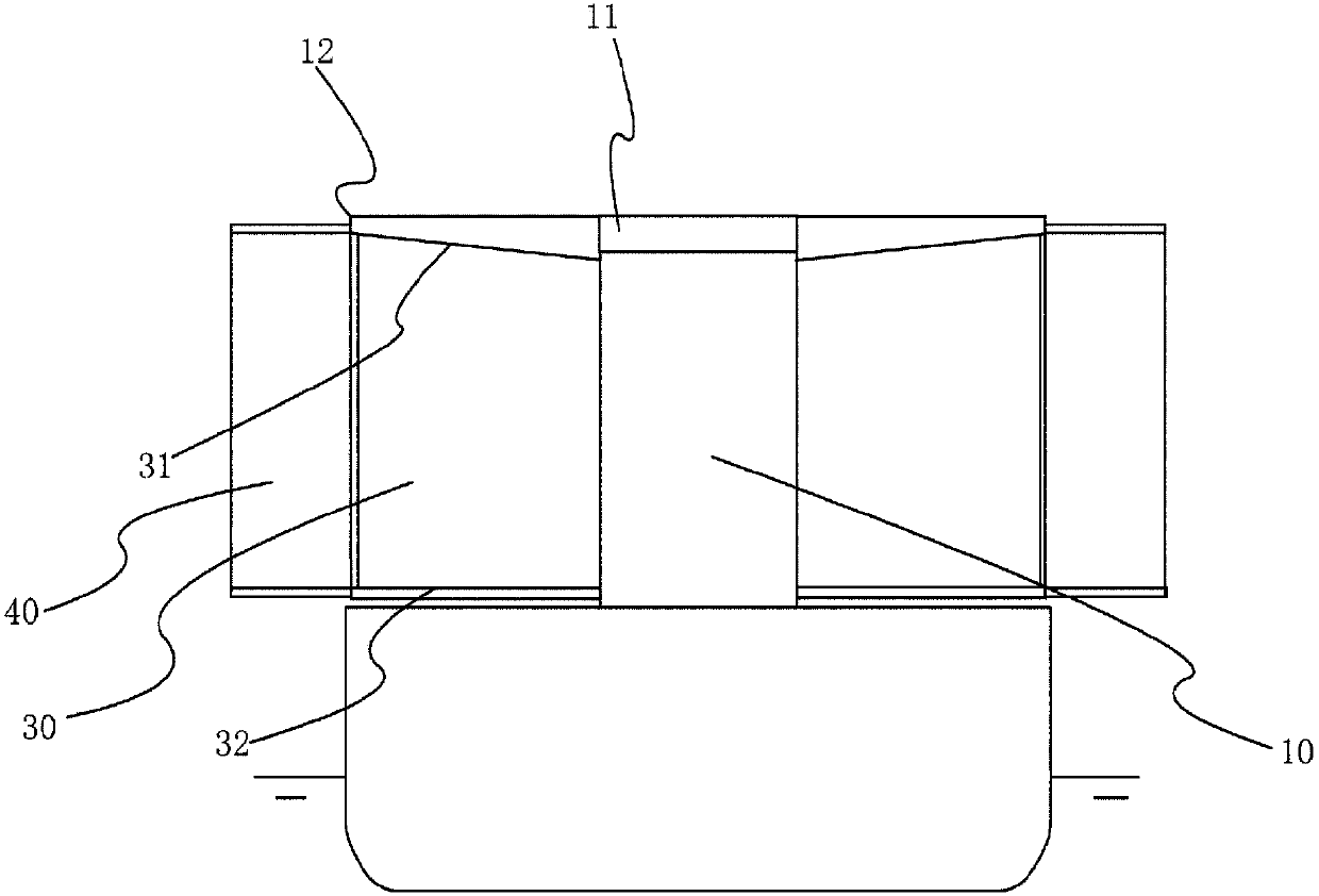
[0088] Hereinafter, the hybrid ship which makes auxiliary use of the wind propulsion force in embodiment of this invention is demonstrated. Figure 1A It is a schematic side view of the whole hybrid ship used in one embodiment of the present invention. Figure 1B It is a schematic plan view of the whole hybrid ship used in one embodiment of the present invention.

[0089] Figure 1A , 1B Even if the illustrated ship 1 is enlarged, the number of sailors hardly increases compared with that of a small ship, and thus the living area of ​​the personnel hardly increases. In addition, in order to maintain the line of sight from the bridge, the position of the bridge is raised, and the shape resistance caused by the wind of the ship is considered, and the overall structure of the living area is made higher. Larger spaces can be created between the two sides of the zone, but this space is not used for energy-saving purposes. In one embodiment, for the purpose of saving energy, the pr...


PUM


Abstract

Provided is a merchant ship in which the bridge is situated astern in the conventional manner, the deck is not occupied by sailing equipment, ports can be placed freely and unrestrictedly and with noincrease to the burden during loading and unloading, cargo space is not strained by sailing equipment accessories below deck, the view from the bridge is not impeded even if the sail is greatly enlarged, and the use of wind power is promoted to conserve fuel and thus prevent air pollution. The invention is a hybrid ship using wind-powered propulsive force as an auxiliary in addition to a main engine and a propulsion system driven by the main engine, wherein the stern section comprises a tower having living quarters and thereabove a bridge (11) which is a workstation for sea voyaging and piloting, and wherein a sail (30) can be deployed laterally, the sail (30) being able to be retracted into a side-wall section of the living quarters in an airspace above a deck (6) and below the floor surface of the bridge (11), to the side of the living quarters of the tower.

Description

technical field [0001] The present invention relates to a ship in which wind power is auxiliary used for propulsion of the ship, in which the residential area is towered, and the area between the residential tower and both sides is provided with a larger space The sail and sail deployment equipment for utilizing wind force mainly utilize the tailwind from the stern direction. The present invention is a ship invention that can save fuel costs, prevent air pollution, and is suitable for commercial ships, especially wide-body ships. Background technique [0002] Wind power has been used to keep ships sailing for a long time, before mechanical power was used for ship propulsion. In the early days, it was a simple and small sailing ship, but due to the increase in size of the sail, the advancement of sailing methods, the advancement of technology using multiple sails, the improvement of the strength of the sail and the strength of the mast, it is possible to achieve faster and la...

Claims


Application Information

Patent Timeline
Patent Type & Authority Applications(China)
IPC IPC(8): B63H9/06
CPCB63H9/06B63B15/00B63H21/20Y02T70/5236B63B2035/009B63H9/067
Inventor 森元信吉
Owner 森元信吉
Why Eureka
Try Eureka