
Gamma source inverter based on switch capacitor and modulation method

A technology of switched capacitors and inverters, which is applied to conversion equipment without intermediate conversion to AC, electrical components, high-efficiency power electronic conversion, etc., can solve device damage, large resonant current, and Z-source inverter boost capability limitations And other issues

Active Publication Date: 2018-01-19
HARBIN INST OF TECH
View PDF7 Cites 2 Cited by
  • Summary
  • Abstract
  • Description
  • Claims
  • Application Information

AI Technical Summary

Problems solved by technology

[0005] The present invention aims to solve the problem that the existing Z-source inverter has the problem that the step-up capability is limited by the straight-through ratio and the modulation degree, and when starting up, a large resonance current is generated, resulting in damage to the device.

Method used


Image

  • Gamma source inverter based on switch capacitor and modulation method
  • Gamma source inverter based on switch capacitor and modulation method
  • Gamma source inverter based on switch capacitor and modulation method

Examples


specific Embodiment approach 1

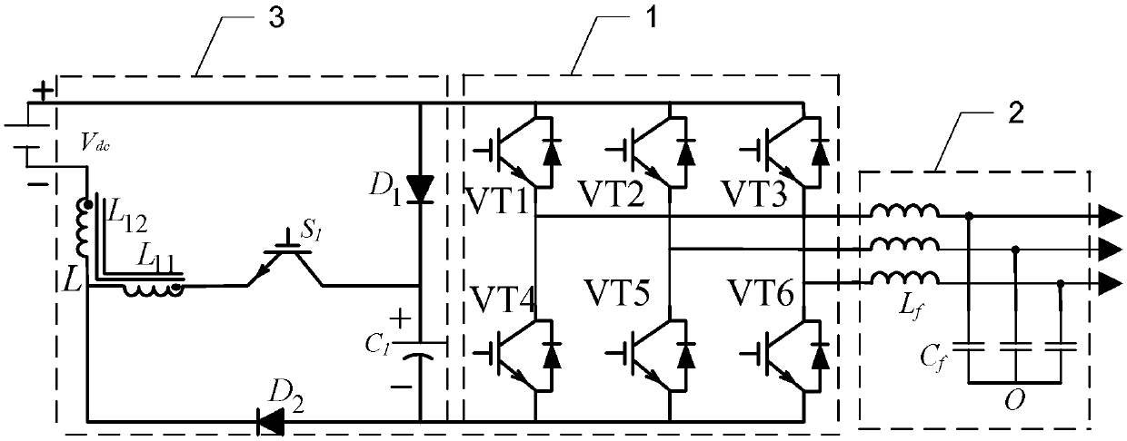
[0075] Specific implementation mode one: see figure 2 Describe this embodiment, the Γ source inverter based on switched capacitors described in this embodiment includes a three-phase inverter 1 and an output filter 2, and also includes a Γ source network module 3 based on switched capacitors;

[0076] DC power V dc The output voltage is sequentially subjected to space voltage modulation by the Γ source network module 3 based on the switched capacitor, voltage inversion by the three-phase inverter 1 and filtering by the output filter 2, and the output reference voltage vector U out , to achieve the DC power supply V dc boost and power the load.

specific Embodiment approach 2

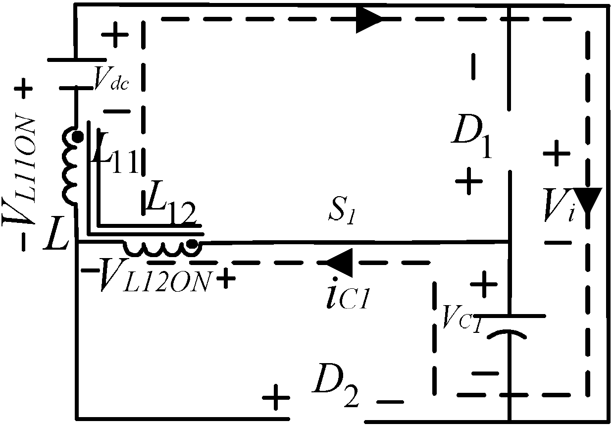
[0077] Specific implementation mode two: see figure 2 Describe this embodiment, the difference between this embodiment and the switched capacitor-based Γ source inverter described in the first specific embodiment is that the switched capacitor-based Γ source network module 3 includes a polar capacitor C 1 , coupled inductor L, diode D 1 , Diode D 2 and IGBT S 1 ,

[0078] DC power V dc The voltage at the positive output terminal and the diode D 1 The positive pole of the three-phase inverter 1 is connected to the voltage positive pole input terminal of the three-phase inverter 1,

[0079] DC power V dc The voltage negative output end of the coupled inductor L is connected with the same name end of the secondary winding,

[0080] The opposite end of the secondary winding of the coupled inductor L is connected to the opposite end of the primary winding,

[0081] The same name terminal of the primary winding of the coupled inductor L and the insulated gate bipolar transi...

specific Embodiment approach 3

[0084] Specific implementation mode three: see Figure 2 to Figure 6 Describe this embodiment, the difference between this embodiment and the switched capacitor-based Γ source inverter described in Embodiment 1 is that the value range of the turns ratio of the primary winding and the secondary winding of the coupled inductor L is within 1 to 2.


PUM


Abstract

The invention provides a gamma source inverter based on a switch capacitor and a modulation method, belonging to the technical field of inverters. The problem that the boosting capability of a Z-source inverter in the prior art is limited by straight-through ratio and modulation degree, and when the inverter is started, large resonance current is generated to cause the damage of the device. The gamma source inverter comprises a three-phase inverter, an output filter and a gamma source network module based on the switch capacitor; and the voltage output by a direct-current power supply Vdc is sequentially subjected to spatial voltage modulation by the gamma source network module based on the switch capacitor, the voltage inversion by the three-phase inverter and the filtering by the outputfilter, and a reference voltage vector Uout is output, the direct-current power supply Vdc is boosted, and power is supplied to the load. The inverter is mainly applied to a new energy power supply system.

Description

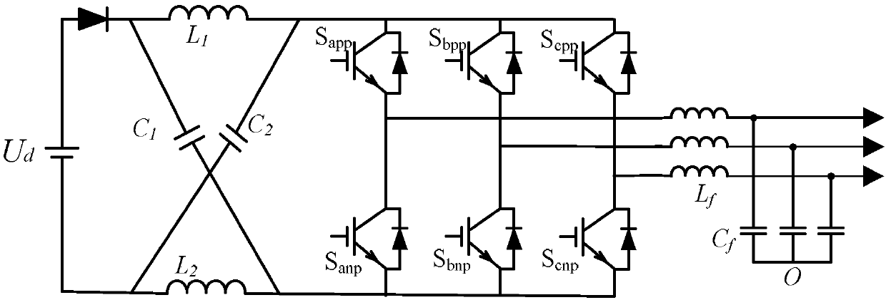
technical field [0001] The invention belongs to the technical field of inverters. Background technique [0002] In the energy conversion and transmission process of new energy power generation, the inverter is very important. However, the traditional voltage source and current source inverters cannot realize step-up and step-down control at the same time, so the application is greatly limited. If a DC-DC converter is added to the DC side, the loss and cost will be increased. At the same time, in order to avoid the same For the occurrence of the bridge arm shoot-through phenomenon, it is necessary to add dead time, which will lead to distortion of the output waveform. [0003] In order to solve the above problems, a Z-source inverter with buck-boost function is proposed, such as figure 1 As shown, by improving the inverter modulation strategy of the three-phase inverter, the boost function is realized by using the through state of the upper and lower bridge arms, and the de...

Claims


Application Information

Patent Timeline
IPC IPC(8): H02M7/5387H02M1/12H02M3/07
CPCY02B70/10
Inventor 刘洪臣纪玉亮
Owner HARBIN INST OF TECH
Learn More