
Dielectric filter with adjustable coupling and dielectric resonator mixed and matched with metal resonator

A technology of dielectric resonators and metal resonators, which is applied in the field of filters, can solve problems such as insufficient precision, many times of rework, and size deviation of coupling plates, and achieve the effects of improving work efficiency, consistency and stability

Inactive Publication Date: 2018-01-19
苏州灿勤通讯技术有限公司
View PDF6 Cites 0 Cited by
  • Summary
  • Abstract
  • Description
  • Claims
  • Application Information

AI Technical Summary

Problems solved by technology

[0002] In the dielectric filter with a mix of dielectric resonators and metal resonators, the traditional solution is to add a coupling conversion plate between the dielectric resonator and the metal resonator for energy coupling. After the positioning plate is positioned, there are still some Disadvantages, such as the dielectric filter mixed with the dielectric resonator and the metal resonator, there is a dimensional deviation in the assembly of the whole machine, or the precision is not enough, so it needs to be reworked
The current method is to open the filter cover, re-correct the coupling plate, correct the distance between the coupling plate and the dielectric resonator, adjust the accuracy, install it, install the cover plate, and continue debugging. To continue the above work, this method will produce some adverse factors: 1. The deviation of the size of the coupling plate will cause insufficient precision, resulting in difficult debugging, unsatisfactory index debugging, more rework times, time-consuming and laborious, and coupling in the rework process. Dimensions of tabs can change, coupling tabs can break, cavity set screws can break

Method used


Image

  • Dielectric filter with adjustable coupling and dielectric resonator mixed and matched with metal resonator
  • Dielectric filter with adjustable coupling and dielectric resonator mixed and matched with metal resonator

Examples


Embodiment Construction

[0014] The technical solutions in the embodiments of the present invention will be described in detail below in conjunction with the accompanying drawings in the embodiments of the present invention. Obviously, the described embodiments are only some of the embodiments of the present invention, not all of them. Based on the embodiments of the present invention, all other embodiments obtained by persons of ordinary skill in the art without making creative efforts belong to the protection scope of the present invention.

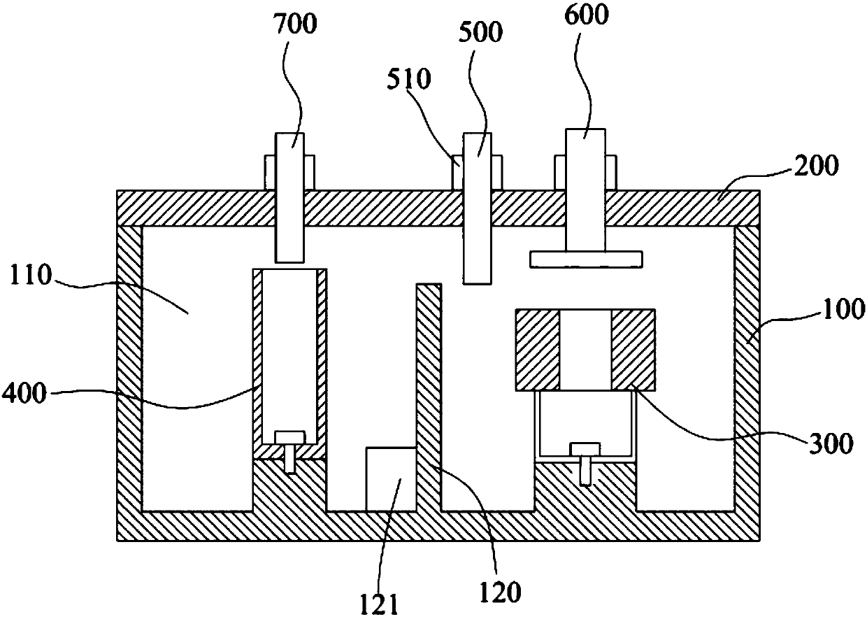
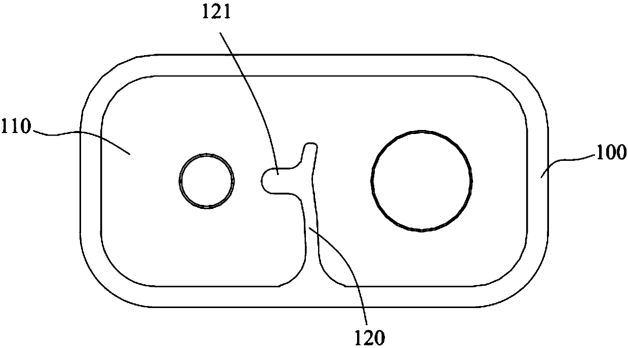
[0015] combine figure 1 and figure 2 As shown, the dielectric filter with adjustable coupling dielectric resonator and metal resonator mix includes a housing 100, a cover plate 200, a dielectric resonator 300 and a metal resonator 400, and an opening cavity 110 is recessed at the top of the housing 100 , the cover plate 200 is detachably fixed on the opening end of the cavity 110, the dielectric resonator 300 and the metal resonator 400 are arranged side by s...


PUM


Abstract

The invention discloses a dielectric filter with adjustable coupling and a dielectric resonator mixed and matched with a metal resonator. The dielectric filter comprises a shell, a cover board, the dielectric resonator and the metal resonator, an open cavity is formed in the top of the shell in a concave mode, the cover board is detachably fixed to the open end of the cavity, the dielectric resonator and the metal resonator are arranged in the cavity in parallel, a coupling block is arranged on the inner wall of the cavity in an inward protruding and extending mode, the side, close to the metal resonator, of the coupling block protrudes and extends to a boss, the coupling block is arranged between the dielectric resonator and the metal resonator, and the side, close to the coupling block,of the dielectric resonator is provided with an adjustable threaded rod. According to the filter, a traditional coupling and transformation piece is replaced by the coupling block, and the coupling block and the shell can be integrated, so that the consistency and the stability of the coupling block are improved; by arranging the adjustable threaded rod, adjustable production is achieved, and theworking efficiency is improved.

Description

technical field [0001] The present application relates to a filter, in particular to a dielectric filter mixed with adjustable coupling dielectric resonators and metal resonators. Background technique [0002] In the dielectric filter with a mix of dielectric resonators and metal resonators, the traditional solution is to add a coupling conversion plate between the dielectric resonator and the metal resonator for energy coupling. After the positioning plate is positioned, there are still some Disadvantages, such as the dielectric filter mixed with the dielectric resonator and the metal resonator, there is a dimensional deviation in the assembly of the whole machine, or the precision is not enough, and it needs to be reworked. The current method is to open the filter cover, re-correct the coupling plate, correct the distance between the coupling plate and the dielectric resonator, adjust the accuracy, install it, install the cover plate, and continue debugging. To continue t...

Claims


Application Information

Patent Timeline
IPC IPC(8): H01P1/20
Inventor 张远飞
Owner 苏州灿勤通讯技术有限公司
Learn More