
Iron part, display device and stamping die for preparing iron part

A technology for stamping dies and display devices, which is applied in the field of stamping dies, can solve problems that need to be improved, and achieve the effects of easy recognition by human eyes and improved alignment accuracy

Active Publication Date: 2018-01-19
BOE TECH GRP CO LTD +1
View PDF9 Cites 0 Cited by
  • Summary
  • Abstract
  • Description
  • Claims
  • Application Information

AI Technical Summary

Problems solved by technology

[0003] However, the current iron parts, display devices, and stamping dies for preparing iron parts still need to be improved

Method used


Image

  • Iron part, display device and stamping die for preparing iron part
  • Iron part, display device and stamping die for preparing iron part
  • Iron part, display device and stamping die for preparing iron part

Examples


Embodiment Construction

[0024] Embodiments of the present invention are described in detail below, examples of which are shown in the drawings, wherein the same or similar reference numerals designate the same or similar elements or elements having the same or similar functions throughout. The embodiments described below by referring to the figures are exemplary only for explaining the present invention and should not be construed as limiting the present invention.

[0025] In the description of the present invention, the orientations or positional relationships indicated by the terms "upper", "lower" and the like are based on the orientations or positional relationships shown in the accompanying drawings, which are only for the convenience of describing the present invention and do not require that the present invention must be based on a specific Azimuth configuration and operation, therefore, should not be construed as limiting the invention.

[0026] In one aspect of the invention, the invention ...


PUM

PropertyMeasurementUnit
Widthaaaaaaaaaa

Abstract

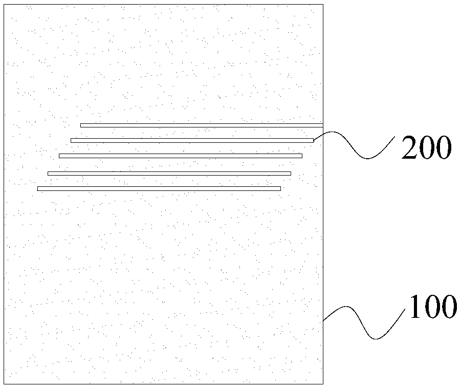
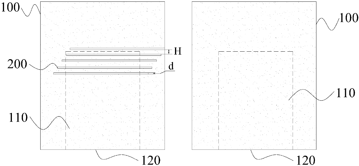
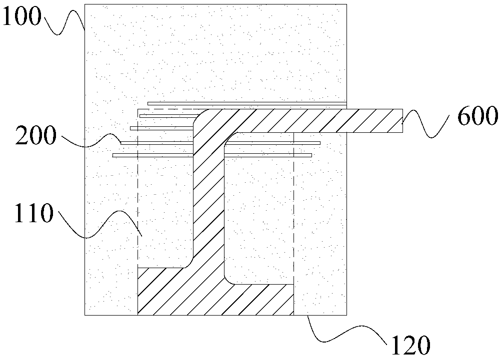
The invention discloses an iron part, a display device and a stamping die for preparing the iron part. The iron part comprises a base body, and the surface of one side of the base body is provided with multiple circuit position lines. Thus, the iron part is simple in structure; the position of a bent flexible printed circuit board can be detected with the circuit position lines, the alignment precision is improved, and meanwhile an identification and classification method is provided for grading liquid crystal modules according to different levels of bending precision.

Description

technical field [0001] The invention relates to the field of liquid crystal display, in particular to an iron piece, a display device, and a stamping die for preparing the iron piece. Background technique [0002] With the development of technology, the market has higher and higher requirements for LCD module products. The liquid crystal module includes a liquid crystal display panel and a backlight module. The backlight module emits uniform surface light, and the light is irradiated into human eyes through the liquid crystal display panel. The liquid crystal display panel processes incident light on a pixel-by-pixel basis to display images. In addition, the liquid crystal module also includes iron frames, iron parts and other components, which are used to fix the liquid crystal display panel and wrap around components such as flexible circuit boards. The flexible circuit board or printed circuit board on the liquid crystal display panel is in contact with one side of the ...

Claims


Application Information

Patent Timeline
IPC IPC(8): G02F1/133G02F1/1333B21D37/10
Inventor 许景欣
Owner BOE TECH GRP CO LTD
Learn More