
Side adjustment oil buffer

A technology of hydraulic buffers and adjustment components, which is applied to shock absorbers, shock absorbers, liquid shock absorbers, etc., can solve the problems of relatively complex structure, high processing difficulty, blind area of ​​scale vision, etc., and achieves reasonable structure simplification, Easy to assemble and accurate alignment adjustment

Pending Publication Date: 2018-01-19
C JAC IND CO LTD
View PDF0 Cites 2 Cited by
  • Summary
  • Abstract
  • Description
  • Claims
  • Application Information

AI Technical Summary

Problems solved by technology

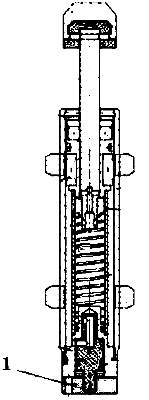
[0002] With the development of automation technology, oil pressure buffers are adopted by more equipment, see attached figure 1 As shown, the existing hydraulic shock absorber adopts the rear-mounted adjustment knob method. This structure is relatively simple, but the adjustment range of the adjustment knob 1 is greater than 180°. After the product is installed, it is easy to produce blind spots in the field of vision, and the user cannot see all the scale lines. Therefore, during installation, the adjustment knob 1 is exposed to the outside, so that the scale can be adjusted later
The existing buffer also has a pre-adjusted structure, which is relatively complex in structure, difficult to process, and prone to blind spots in the scale field of view

Method used


Image

  • Side adjustment oil buffer
  • Side adjustment oil buffer
  • Side adjustment oil buffer

Examples


Embodiment

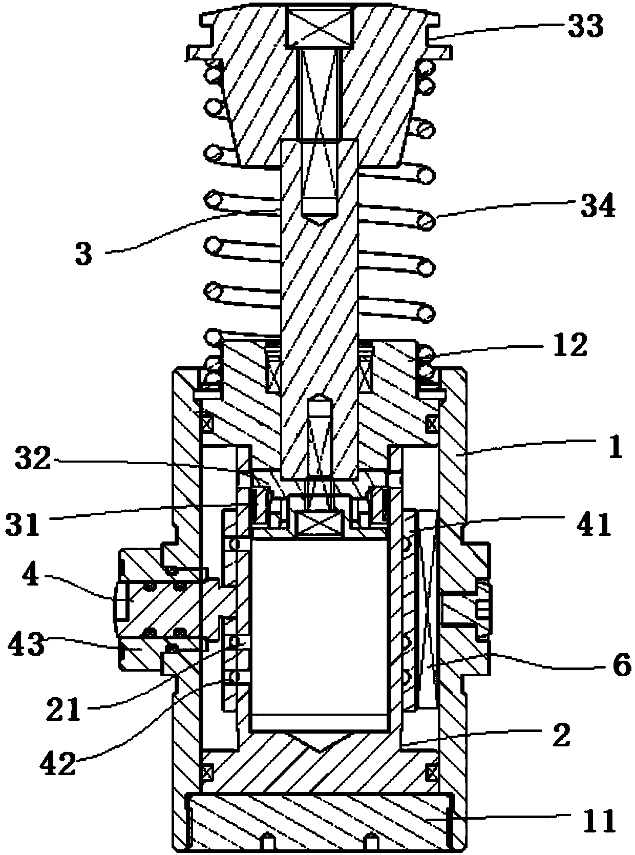
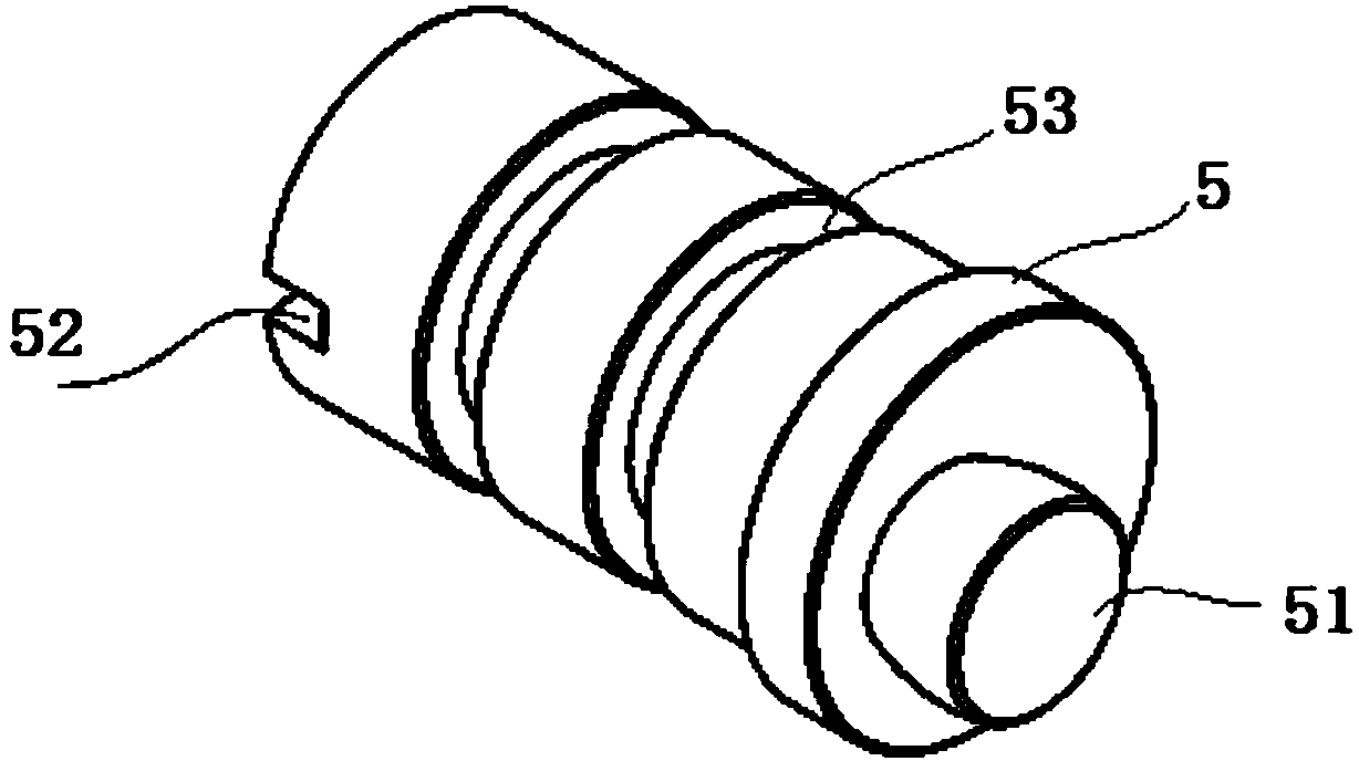
[0019] refer to Figure 2-3 As shown, this embodiment is a side-adjustable hydraulic buffer, including a cylinder assembly, a buffer assembly located in the cylinder assembly, an adjustment assembly, and a liquid contained in the cylinder assembly. The liquid is hydraulic Oil. The cylinder body assembly includes an outer cylinder 1 and an inner cylinder 2 arranged in the outer cylinder 1 and axially consistent with it. One end of the outer cylinder 1 is detachably fixed with an end cover 11 , and the other end of the outer cylinder 1 is detachably fixed with a bushing 12 . The inner end of the inner cylinder 2 abuts against the end cover 11 , the outer end of the inner cylinder 2 abuts against the bushing 12 , and a buffer cavity is formed between the inner cylinder 2 and the outer cylinder 1 .

[0020] The buffer assembly includes a piston rod 3 inserted into the inner cylinder 2 through the bushing 12 , and a piston 31 arranged at the inner end of the piston rod 3 . A pis...


PUM


Abstract

The invention discloses a side adjustment oil buffer. The side adjustment oil buffer comprises a cylinder body component, a buffer component arranged in the cylinder body component, an adjustment component and a liquid accommodated in the cylinder body component, and is characterized in that the cylinder body component comprises an outer cylinder and an inner cylinder arranged in the outer cylinder, wherein an end cap is arranged at one end of the outer cylinder; a bushing is arranged at the other end of the outer cylinder; the inner end of the inner cylinder is propped against the end cap; the outer end of the inner cylinder is propped against the bushing; the adjustment component comprises an adjustment bolt and an adjustment sleeve arranged on the outer wall of the inner cylinder; the adjustment bolt is inserted into the outer cylinder in the radial direction; an eccentric lug boss on the adjustment bolt is clamped with the adjustment sleeve; an adjustment hole is formed in the adjustment sleeve; a throttling hole is formed in the inner cylinder; the eccentric lug boss rotates to enable the adjustment sleeve to be displaced; and the adjustment hole can relatively adjust the cross section of the throttling hole. A visual dead zone is avoided during adjustment of a throttling area.

Description

technical field [0001] The invention belongs to the technical field of buffers, in particular to a side-adjustable oil pressure buffer. Background technique [0002] With the development of automation technology, oil pressure buffers are adopted by more equipment, see attached figure 1 As shown, the existing hydraulic shock absorber adopts the rear-mounted adjustment knob method. This structure is relatively simple, but the adjustment range of the adjustment knob 1 is greater than 180°. After the product is installed, it is easy to produce blind spots in the field of vision, and the user cannot see all the scale lines. Therefore, during installation, the adjustment knob 1 is exposed to the outside, so that the scale can be adjusted later. The existing buffer also adopts a pre-adjusted structure, which is relatively complex in structure, difficult to process, and prone to blind spots in the scale field of view. Contents of the invention [0003] The object of the present ...

Claims


Application Information

Patent Timeline
Patent Type & Authority Applications(China)
IPC IPC(8): F16F9/19F16F9/44
Inventor 杨涛
Owner C JAC IND CO LTD
Learn More