
Vibration damping battery box for new energy automobiles

A technology for new energy vehicles and battery boxes, which is applied to battery pack components, circuits, electrical components, etc., can solve the problems of no shock absorption device, long waste of time, and extremely inconvenient screw disassembly and assembly, so as to reduce the impact and facilitate the The effect of heat dissipation and saving time for battery replacement

Active Publication Date: 2018-01-19
泰州市扬帆车件有限公司
View PDF7 Cites 5 Cited by
  • Summary
  • Abstract
  • Description
  • Claims
  • Application Information

AI Technical Summary

Problems solved by technology

[0003] However, the batteries of existing cars are generally connected to the battery box in the car by multiple bolt fixing devices. During the replacement process, all the bolts need to be removed and the newly replaced battery must be refastened in the battery box by bolts. It is relatively easy to disassemble and assemble the bolts close to the disassembly personnel, but it is extremely inconvenient to disassemble and assemble the screws far away from the disassembly personnel, even between the battery and the battery box. This battery replacement method is cumbersome and wastes a lot of time during the operation. Moreover, there is no shock absorbing device in the current battery box, and the battery is easily damaged when encountering vibration, so it is necessary to improve it

Method used


Image

  • Vibration damping battery box for new energy automobiles
  • Vibration damping battery box for new energy automobiles
  • Vibration damping battery box for new energy automobiles

Examples


Embodiment Construction

[0024] The specific implementation manners of the present invention will be further described in detail below in conjunction with the accompanying drawings and embodiments. The following examples are used to illustrate the present invention, but are not intended to limit the scope of the present invention.

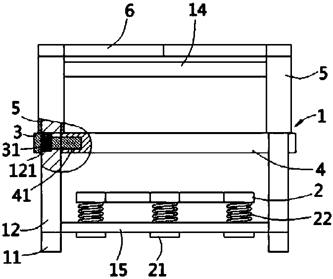
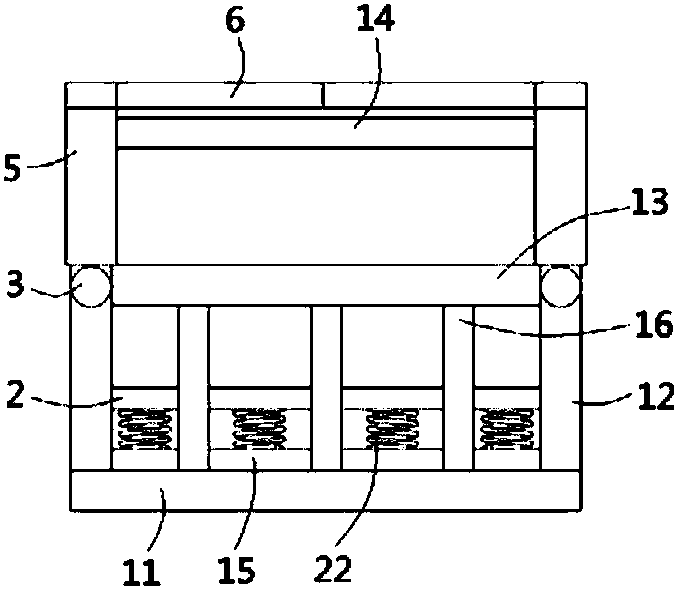
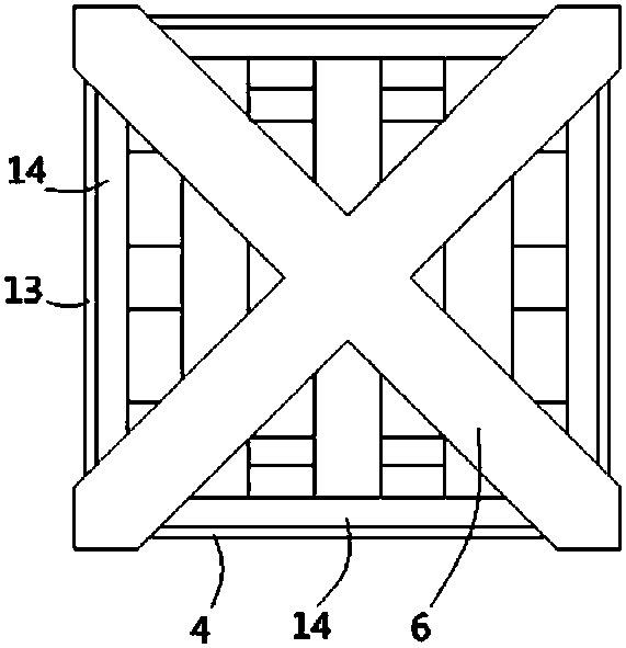
[0025] see figure 1 , figure 2 , Figure 4 , a shock-absorbing battery box applied to new energy vehicles according to the present invention includes a box body 1, and the box body includes a pair of bottom bars 11, uprights 12 fixed at both ends of the bottom bar 11, fixed at the bottom The support beams 13 between the adjacent columns 12 above the bar 11, the top beams 14 fixed between the adjacent columns 12, and some crossbeams 15 whose two ends are respectively fixed on a pair of bottom poles 11, the crossbeams 15 are inserted A number of inverted T-shaped guide posts 21 are connected, the upper ends of the guide posts 21 are fixed on the supporting plate 2, and s...


PUM


Abstract

The invention discloses a vibration damping battery box for new energy automobiles. The vibration damping battery box includes a box body; the box body includes a pair of bottom rods, vertical columnsfixed on two ends of the bottom rods, supporting beams fixed between the adjacent vertical columns above the bottom rods, top beams fixed between the adjacent vertical columns, and a plurality of cross beams, wherein two ends of the cross beams are fixed on the pair of bottom rods; a plurality of reversed T-shaped guide columns are inserted into the cross beams; upper ends of the guide columns are fixed on a supporting plate; the guide columns are sleeved with damping springs; T-shaped telescopic rods are inserted into the vertical columns; the telescopic rods are sleeved by telescopic springs; the vertical columns above the supporting beams are sleeved by column sleeves; X-shaped pressing plates are fixed on upper ends of the column sleeves; two vertical avoiding grooves are formed in the column sleeves; vertical racks are formed in right-angle inner walls of the column sleeves; gears are hinged to upper ends of the vertical columns; and one ends of the gears are engaged with the racks. The vibration damping battery box can allow quick demounting of a battery, can save the battery changing time, and can avoid vibration influence on the battery.

Description

Technical field: [0001] The invention relates to the technical field of new energy vehicles, in particular to a shock-absorbing battery box applied to new energy vehicles. Background technique: [0002] The shortage of fossil energy has accelerated the replacement of traditional energy by new energy. As a clean energy, electric energy has been widely used in various fields. At present, electric vehicles have appeared. Electric vehicles mainly use batteries as power carriers. The electric motors on the electric vehicles are driven to rotate through the discharge of the batteries, and then the wheels are driven by the motors to realize the movement of the vehicle. However, the battery capacity of an electric vehicle is limited, and its mileage is still very limited, which requires charging stations on the road, but the charging time of the battery is generally longer, which not only delays the driver's time but also has a Potentially delay passenger journey. A more feasible ...

Claims


Application Information

Patent Timeline
IPC IPC(8): B60K1/04B60S5/06H01M2/10H01M50/249
CPCY02E60/10
Inventor 徐亚维
Owner 泰州市扬帆车件有限公司
Learn More