
Method and device for installing in-hole O-shaped seal ring

A technology of O-shaped sealing ring and mounting hole, which is applied in the direction of hand-held tools and manufacturing tools, can solve the problems of difficult to ensure product quality, easy to scratch fingers, easy to dirty devices, etc., to facilitate disassembly and replacement of tooling, avoid The effect of direct finger contact and stable assembly quality

Pending Publication Date: 2018-01-19
GUANGXI YUCHAI MASCH CO LTD
View PDF6 Cites 5 Cited by
  • Summary
  • Abstract
  • Description
  • Claims
  • Application Information

AI Technical Summary

Problems solved by technology

However, there is a hidden danger that the O-ring does not completely enter the ring groove. When installing the copper sleeve of the fuel injector, the O-ring is prone to be trimmed; It is easy to push the O-ring over the head, beyond the installation position (ring groove) of the O-ring, or even fall to the bottom of the hole. At this time, the O-ring needs to be taken out and reinstalled, resulting in low assembly efficiency; the O-ring is not complete The hidden danger of entering the ring groove, the O-ring is prone to be trimmed when installing the copper sleeve of the fuel injector, the sharp burrs of the ring groove are easy to hurt hands during the operation, and the assembly efficiency is low
The quality hidden danger of incomplete entry into the ring groove occurs, and the O-ring is easily trimmed, making it difficult to ensure product quality
If manual operation, the fingers directly contact with the edge of the ring groove, it is easy to scratch the fingers, not safe enough, easy to dirty the device, and it takes many times to succeed, it is difficult to ensure the assembly quality, and the production efficiency is low

Method used


Image

  • Method and device for installing in-hole O-shaped seal ring
  • Method and device for installing in-hole O-shaped seal ring
  • Method and device for installing in-hole O-shaped seal ring

Examples


Embodiment Construction

[0025] The specific embodiments of the present invention will be described in detail below in conjunction with the accompanying drawings, but it should be understood that the protection scope of the present invention is not limited by the specific embodiments.

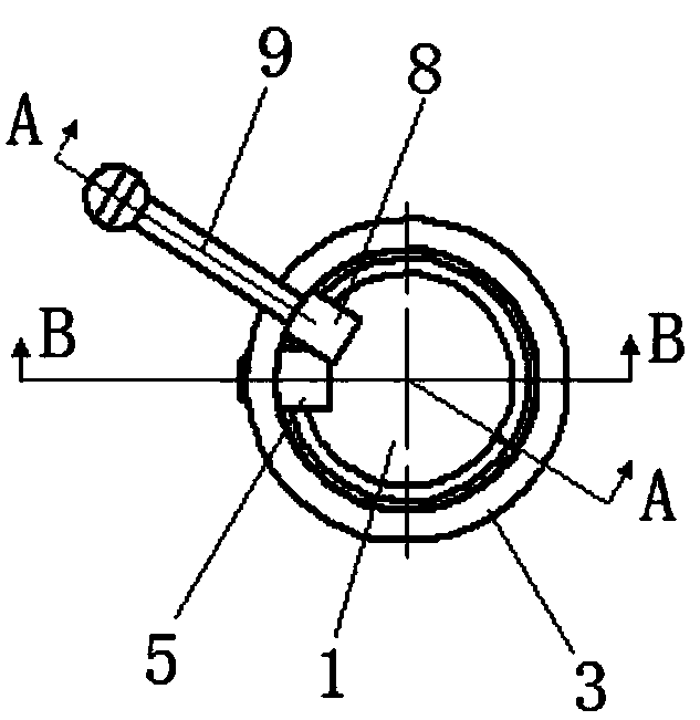
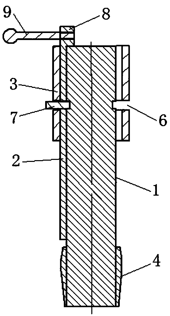
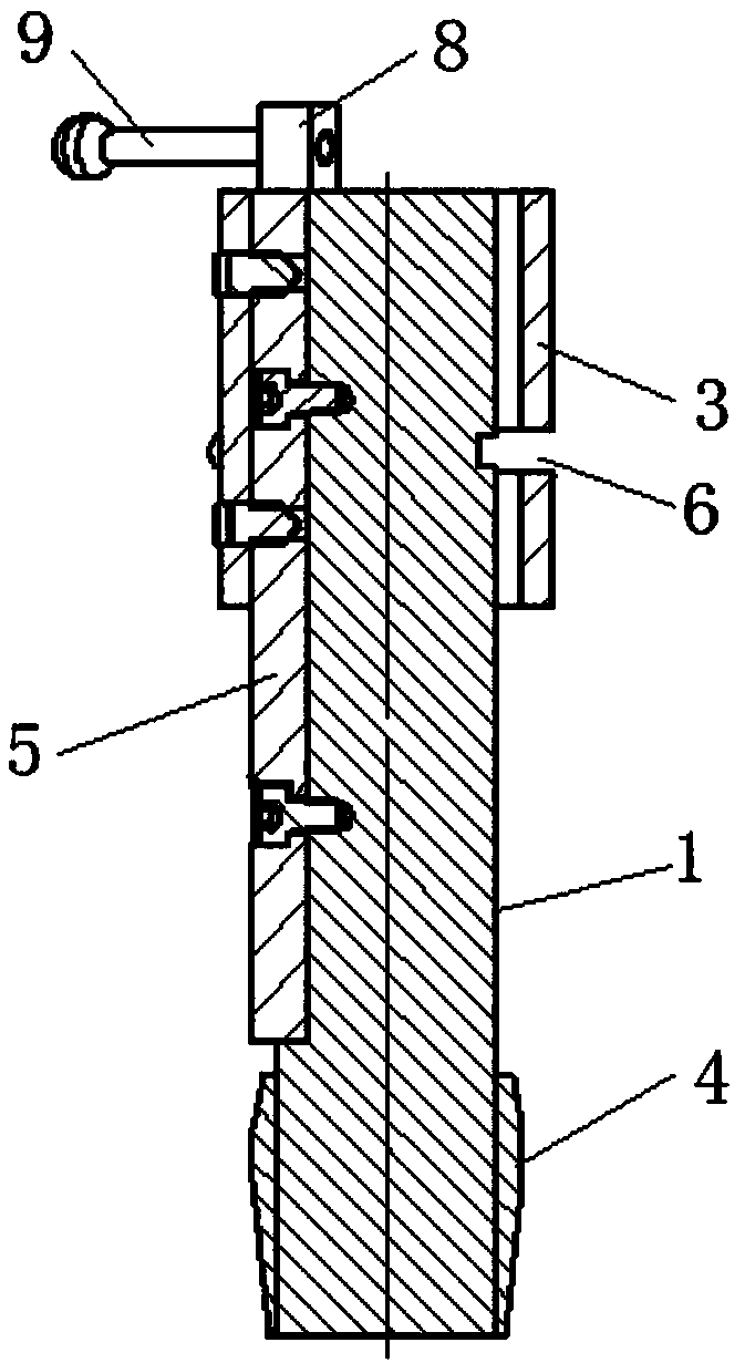
[0026] The specific embodiment of the present invention is like this: as Figure 1-6 As shown, a method for installing an O-ring in a hole includes the following steps: First, a positioning mandrel 1 is set to position the O-ring at its front end, and the positioning mandrel 1 is inserted into the installation hole Make the O-shaped seal ring correspond to the installation groove in the installation hole, insert the positioning mandrel 1 into the bottom of the injector hole, and the O-ring seal on the positioning mandrel 1 corresponds to the installation groove in the hole; then, in A shift fork 2 that can rotate around the cylindrical surface of the positioning mandrel 1 is inserted into the gap between the positionin...


PUM


Abstract

The invention discloses a method for installing an in-hole O-shaped seal ring. The method comprises the following steps that firstly, a locating mandrel is arranged, the front end of the locating mandrel is sleeved with the O-shaped seal ring positionably, and the locating mandrel is inserted into an installing hole, so that the O-shaped seal ring corresponds to an installing groove in the installing hole; and then a shifting fork capable of rotating around the cylindrical face of the locating mandrel is inserted into the gap between the locating mandrel and the installing hole, so that an inner ring of the O-shaped seal ring is extruded, thereby entering the installing groove in the installing hole completely, the locating mandrel is taken out, and installing work of the in-hole O-shapedseal ring is completed. A device for installing the in-hole O-shaped seal ring is further provided. According to assembly of the in-hole O-shaped seal ring, direct contact of fingers can be avoided, hand injury is prevented, assembly quality is stable, success is achieved once, and production efficiency is high.

Description

technical field [0001] The invention relates to the field of engine assembly, more specifically, it relates to a method and a device for installing an O-ring in a hole. Background technique [0002] Currently installing O-rings is a manual operation. Put the O-ring on the orifice of the fuel injector first, then use your index finger to push into the hole until it reaches the ring groove, press one side of the O-ring into the ring groove, and then use your index finger to slide along the ring groove Let the O-ring fully enter the ring groove. [0003] Although the cost of the existing installation method is relatively low, there is no tooling cost, and the operation is simple. However, there is a hidden danger that the O-ring does not completely enter the ring groove. When installing the copper sleeve of the fuel injector, the O-ring is prone to be trimmed; It is easy to push the O-ring over the head, beyond the installation position (ring groove) of the O-ring, or even f...

Claims


Application Information

Patent Timeline
IPC IPC(8): B25B27/02
Inventor 梁敏李如苹梁晓非
Owner GUANGXI YUCHAI MASCH CO LTD
Learn More