
Cable sealing device

A cable sealing and cable technology, which is applied in the direction of cable inlet sealing device, etc., can solve the problem of unusable sealing parts, and achieve the effect of installation and sealing connection, high reliability of sealing connection, and fewer parts

Pending Publication Date: 2018-01-16
SUZHOU NUCLEAR POWER RES INST +2
View PDF11 Cites 3 Cited by
  • Summary
  • Abstract
  • Description
  • Claims
  • Application Information

AI Technical Summary

Problems solved by technology

At the same time, one end of the sensor is in the high-pressure chamber, and the other end passes through the high-pressure chamber and is located outside the high-pressure chamber. The middle cable part is just the part that needs to be sealed, and commonly used devices for high-pressure sealing such as ferrule joints etc. Sealing parts cannot be used at this time

Method used


Image

  • Cable sealing device
  • Cable sealing device
  • Cable sealing device

Examples


Embodiment Construction

[0032] The technical solutions of the present invention will be further described below in conjunction with the accompanying drawings and specific embodiments.

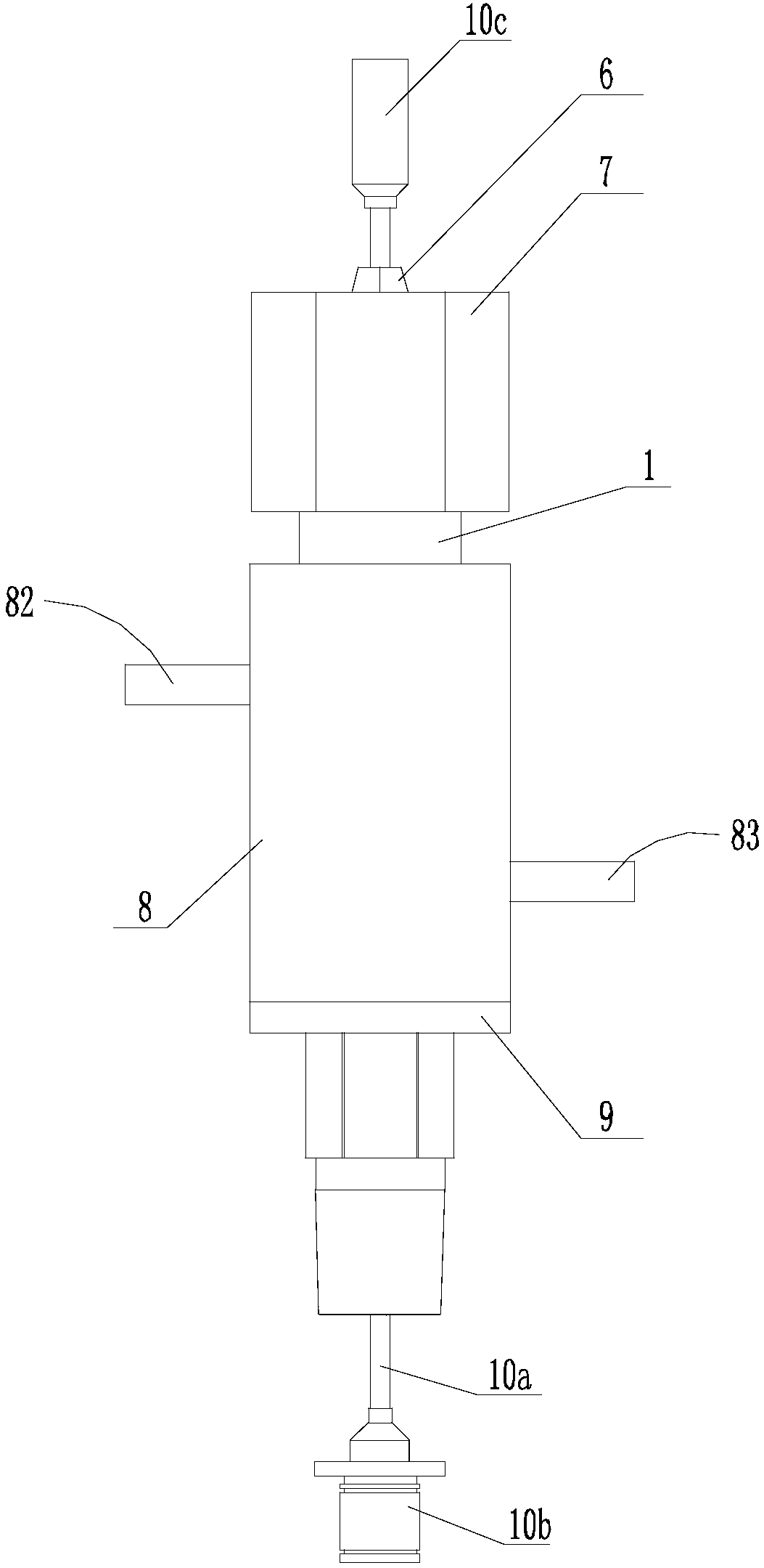
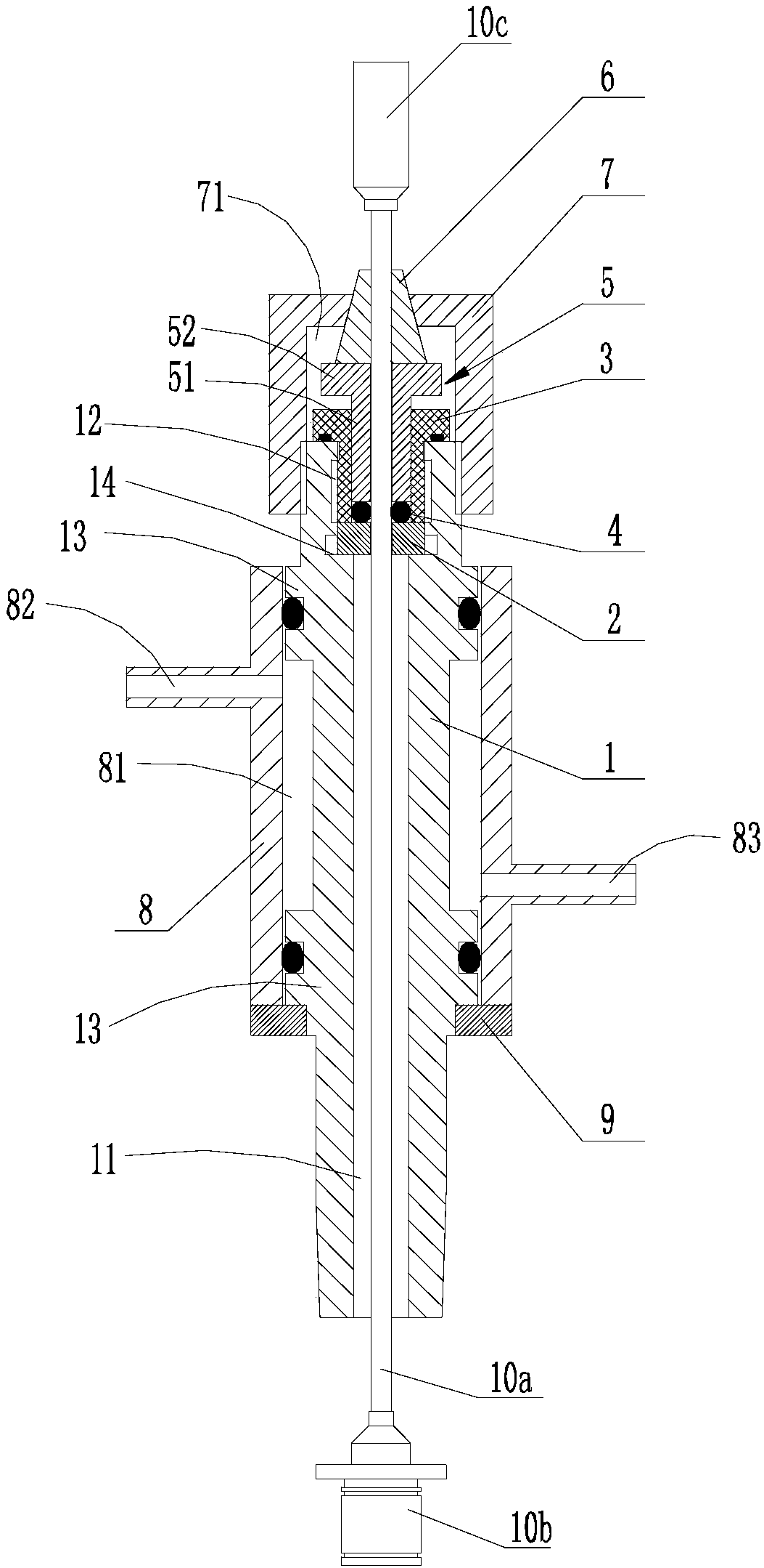
[0033] see figure 1 As shown, the sensor 10 includes a cable 10a, a detection head 10b fixed at one end of the cable 10a, and an output terminal 10c fixed at the other end of the cable 10a, wherein the detection head 10b needs to be inserted into the high pressure and / or high temperature environment chamber of the high pressure container , the output terminal 10c is located outside the above-mentioned environmental cavity.

[0034] see Figure 2 to Figure 7 As shown, a cable sealing device, wherein the cable 10a on the sensor 10 extends in the vertical direction, the upper end is provided with the output terminal 10c, and the lower end is provided with the detection head 10b. The structure and installation connection relationship of each component in the sealing device.

[0035] Specifically, see Figure 2 to Figu...


PUM


Abstract

The invention discloses a cable sealing device. The cable sealing device is simple in structure, a few parts are involved, installation and hermetic connection of a dumbbell-shaped sensor can be effectively achieved, so that a probe of the sensor can be arranged in a high-temperature and / or high-voltage environmental cavity for detection, an output terminal of the sensor can be arranged outside the environment cavity and is connected with other equipment to acquire a detection signal. The cable sealing device is convenient to install and is high in hermetic connection reliability.

Description

technical field [0001] The invention relates to a cable sealing device, in particular to a cable sealing device used in high temperature and high pressure environments. Background technique [0002] In order to collect relevant elements in a high-pressure environment, it is usually necessary to extend the probe of the sensor into the high-pressure environment cavity. At present, most of the sensors, one end of which is packaged by soldering, and the other end is connected to the output terminal in order to ensure the stability of the sensor. figure 1 Shown is a dumbbell-shaped structure, that is, a structure in which the middle cable portion of the sensor is smaller than the ends. At the same time, one end of the sensor is in the high-pressure chamber, and the other end passes through the high-pressure chamber and is located outside the high-pressure chamber. The middle cable part is just the part that needs to be sealed, and commonly used devices for high-pressure sealing ...

Claims


Application Information

Patent Timeline
IPC IPC(8): H02G15/013
CPCY02E30/30
Inventor 梅金娜薛飞罗志峰张国栋韩姚磊冯亚飞
Owner SUZHOU NUCLEAR POWER RES INST
Learn More