
Trench gate super-junction MOSFET device and preparation method therefor

A trench gate and trench technology, which is applied in semiconductor/solid state device manufacturing, semiconductor devices, electrical components, etc., can solve the problems of reducing on-resistance, increasing on-resistance, reducing device size, etc., achieving compact structure, reducing On-resistance, the effect of improving avalanche resistance

Inactive Publication Date: 2018-01-16
江苏芯长征微电子集团股份有限公司
View PDF3 Cites 6 Cited by
  • Summary
  • Abstract
  • Description
  • Claims
  • Application Information

AI Technical Summary

Problems solved by technology

[0003] Existing planar gate super junction MOS devices include N+ type substrate, N-type epitaxial layer (N-epi), P-type column deep trench structure (Ppillar trench), gate oxide layer, polysilicon gate (Poly Gate), P Type body region (Pbody); by introducing a deep groove Trench structure inside the device, the lateral P-type column / N-type epitaxial layer depletion can be realized, so that it can be realized under the very low resistivity N-type epitaxial layer High withstand voltage and reduced on-resistance; traditional planar gate super-junction MOSFET, because there is a JFET area in the P-type body interval, it will increase the on-resistance
And due to limitations such as channel length, it is difficult to further reduce the device size

Method used


Image

  • Trench gate super-junction MOSFET device and preparation method therefor
  • Trench gate super-junction MOSFET device and preparation method therefor
  • Trench gate super-junction MOSFET device and preparation method therefor

Examples


Embodiment Construction

[0036] The present invention will be further described below in conjunction with specific drawings and embodiments.

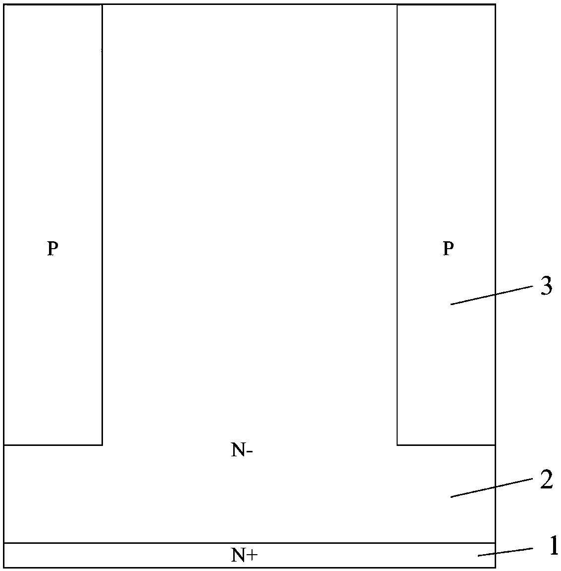
[0037] Such as figure 1 with Picture 9 Shown: In order to effectively reduce the channel resistance and improve the avalanche tolerance, taking the N-type MOSFET device as an example, the present invention includes a semiconductor substrate and a cell area located in the central area of ​​the semiconductor substrate. The semiconductor substrate includes an N+ substrate 1 and a The N-type epitaxial layer 2 above the N+ substrate 1; a super junction structure is arranged in the N-type epitaxial layer 2 in the cell region, and the super junction structure includes a number of alternately distributed N pillars and P pillars 3;

[0038] The P pillar 3 extends vertically downward from the top of the N-type epitaxial layer 2, a cell trench 11 is provided between adjacent P pillars 3, and a P-type base is provided on the outer side and upper side of the cell trench 11 Reg...


PUM


Abstract

The invention relates to a trench gate super-junction MOSFET device and a preparation method therefor. The device comprises a semiconductor substrate and a cellular region positioned in the central region of the semiconductor substrate; the semiconductor substrate comprises a first conductive type substrate and a first conductive type epitaxial layer positioned above the first conductive type substrate; a super-junction structure is arranged in the first conductive type epitaxial layer in the cellular region; second conductive type columns and the first conductive type epitaxial layer can formthe super-junction structure; a cellular trench is formed between the adjacent second conductive type columns; an insulating oxide layer and conductive polysilicon are arranged in each cellular trench; by virtue of the super-junction structure and the trench gate structure, on resistance can be lowered effectively; the first conductive type epitaxial layer outside the cellular trench opening is covered with the insulating oxide layer; the insulating oxide layer outside the cellular trench opening is covered with the conductive polysilicon at the same time; and by virtue of the insulating oxide layer outside the cellular trench opening and the conductive polysilicon, avalanche resistance can be improved, and compact structure and safety and reliability are realized.

Description

Technical field [0001] The invention relates to a MOSFET device and a preparation method thereof, in particular to a trench gate super junction MOSFET device and a preparation method thereof, and belongs to the technical field of semiconductor devices. Background technique [0002] At present, the existing common N-type VDMOS devices include N+ type substrate, N-type epitaxial layer (N-epi), gate oxide layer, poly gate (Poly Gate), P-type body (Pbody); common VDMOS device To improve the withstand voltage, a higher resistivity and thicker N-type epitaxial layer is required, but this will greatly increase the on-resistance of the MOS device. [0003] Existing planar gate super junction MOS devices include N+ type substrate, N-type epitaxial layer (N-epi), P type pillar trench structure (Ppillar trench), gate oxide layer, poly gate (Poly Gate), P Pbody; by introducing a deep trench Trench structure inside the device, the lateral P-type pillar / N-type epitaxial layer can be depleted, w...

Claims


Application Information

Patent Timeline
Patent Type & Authority Applications(China)
IPC IPC(8): H01L29/78H01L29/06H01L21/336
Inventor 徐承福朱阳军
Owner 江苏芯长征微电子集团股份有限公司
Learn More