
Fabrication method of trench Schottky device

A manufacturing method and groove technology, applied in semiconductor/solid-state device manufacturing, electrical components, circuits, etc., can solve the problem of high cost of anode injection process, high requirements of anode injection process, increase of manufacturing cost of trench Schottky devices, etc. problem, to achieve the effect of reducing process cost, high removal efficiency and reducing manufacturing cost

Active Publication Date: 2020-08-07
FOUNDER MICROELECTRONICS INT
View PDF5 Cites 0 Cited by
  • Summary
  • Abstract
  • Description
  • Claims
  • Application Information

AI Technical Summary

Problems solved by technology

[0003] Anode implantation is specifically to implant boron ions into the silicon surface outside the trench, but boron ions cannot be implanted in the trench. Therefore, the process requirements for anode implantation are relatively high, resulting in high process cost of anode implantation and increasing the number of trenches. Manufacturing Cost of Schottky Devices

Method used


Image

  • Fabrication method of trench Schottky device
  • Fabrication method of trench Schottky device
  • Fabrication method of trench Schottky device

Examples


Embodiment Construction

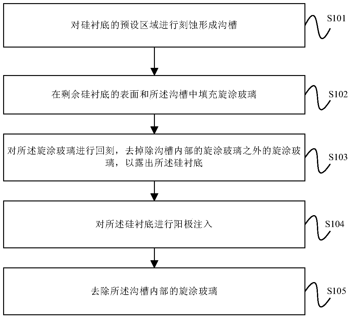
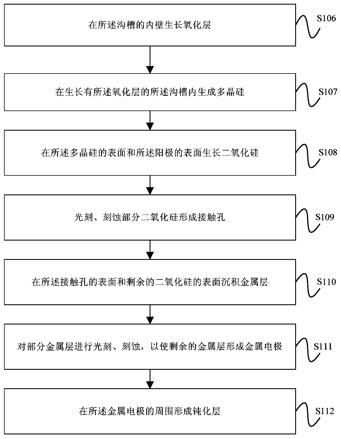
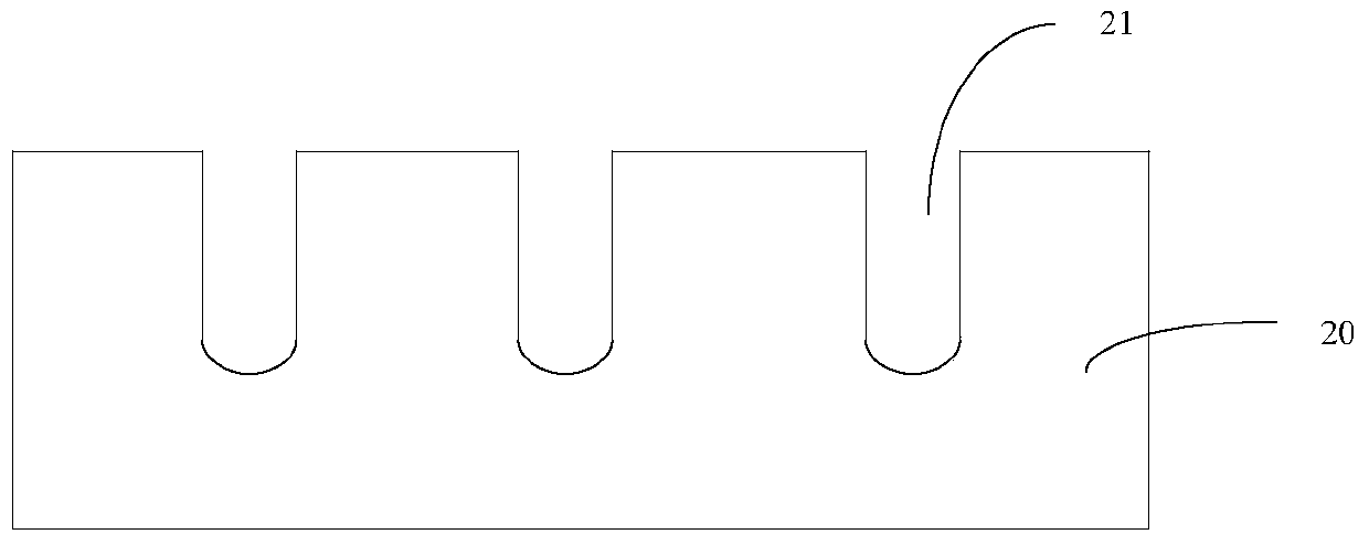
[0029] Figure 1A A flowchart of a method for fabricating a trench Schottky device provided by an embodiment of the present invention. In order to describe the method in this embodiment clearly and systematically, Figure 2-Figure 7 A schematic cross-sectional view of a trench Schottky device during the implementation of the method of the embodiment of the present invention, as shown in Figure 1A As shown, the method includes:

[0030] Step S101, etching a preset region of the silicon substrate to form a trench;

[0031] Coat photoresist on the surface of the silicon substrate, and form grooves by exposing, developing, and etching part of the photoresist. This embodiment does not limit the number of grooves, and the number of optional grooves is as follows Figure 1A 3 shown. The schematic cross-sectional view of the trench Schottky device after performing step S101 is as follows: figure 2 As shown, wherein, the silicon substrate is indicated by 20, and the trench is indic...


PUM

PropertyMeasurementUnit
thicknessaaaaaaaaaa
thicknessaaaaaaaaaa
thicknessaaaaaaaaaa

Abstract

The embodiment of the invention provides a trench Schottky device making method. The method comprises steps: a preset area on a silicon substrate is etched to form a trench; the surface of the remaining silicon substrate and the trench are filled with spin-on glass; the spin-on glass is subjected to back etching to remove the spin-on glass except the spin-on glass inside the trench to expose the silicon substrate; anode injection is carried out on the silicon substrate; and the spin-on glass inside the trench is removed. According to the embodiment of the invention, through filling the spin-onglass in the trench, the trench can be ensured to be fully filled, and boron ions are thus ensured to be only injected to the surface of the silicon substrate. Besides, the process of using hydrofluoric acid to remove the spin-on glass in the trench is low in cost and high in removing efficiency, the anode injection process cost is reduced, and the trench Schottky device making cost is thus reduced.

Description

technical field [0001] Embodiments of the present invention relate to the field of semiconductors, and in particular to a method for manufacturing a trench Schottky device. Background technique [0002] In the production process of semiconductor devices, especially in the manufacture of trench Schottky devices, it is usually necessary to perform anode implantation on the trench Schottky devices to reduce the forward conduction voltage of the trench Schottky devices. [0003] Anode implantation is specifically to implant boron ions into the silicon surface outside the trench, but boron ions cannot be implanted in the trench. Therefore, the process requirements for anode implantation are relatively high, resulting in high process cost of anode implantation and increasing the number of trenches. Manufacturing cost of Schottky devices. Contents of the invention [0004] An embodiment of the present invention provides a method for manufacturing a trench Schottky device, so as ...

Claims


Application Information

Patent Timeline
Patent Type & Authority Patents(China)
IPC IPC(8): H01L21/265
Inventor 贺冠中
Owner FOUNDER MICROELECTRONICS INT
Learn More