Inner rotor aircraft structure

A rotorcraft and rotor technology, applied in the field of aircraft, can solve the problems of insufficient compact structure, enlarged blade size, inability to realize vertical take-off and landing and air suspension, etc., and achieve the effect of compact structure and strong maneuverability

Pending Publication Date: 2018-01-16
袁洪跃
View PDF10 Cites 0 Cited by
  • Summary
  • Abstract
  • Description
  • Claims
  • Application Information

AI Technical Summary

Problems solved by technology

[0002] Traditional aircraft are generally divided into two categories: fixed-wing and rotary-wing. Fixed-wing aircraft fly fast but most of them cannot achieve vertical take-off and landing and air suspension. Although rotor aircraft can achieve vertical take-off and landing and air suspension, their flight speed is not high.
The rotors of most rotorcraft are exposed, and the flight stability is easily affected by airflow disturbances. The exposed rotors pose a threat to the surrounding environment. In order to increase the lift, the size of the blades needs to be increased, which cannot meet the miniaturization requirements.
Some rotorcraft have added ducts to the rotor. Although it can weaken the influence of airflow disturbance to a certain extent, prevent the rotor from harming the surrounding environment, and reduce the size of the blade under the premise of ensuring lift, the rotor part is still separated from the body, and the structure is not enough. Compact without further reduction in size
To sum up, the shortcomings of the traditional aircraft are: the maneuverability and speed cannot be satisfied at the same time, the environmental adaptability is insufficient, and it cannot fly freely and stably in complex three-dimensional spaces such as small cities at low altitudes, forests, and buildings. and suspension
[0004] For the above-mentioned problems existing in related technologies, no other effective solutions have been found yet

Method used


Image

  • Inner rotor aircraft structure
  • Inner rotor aircraft structure
  • Inner rotor aircraft structure

Examples


Embodiment 1

[0039] This embodiment provides a kind of aircraft structure with left and right inner rotors, as follows:

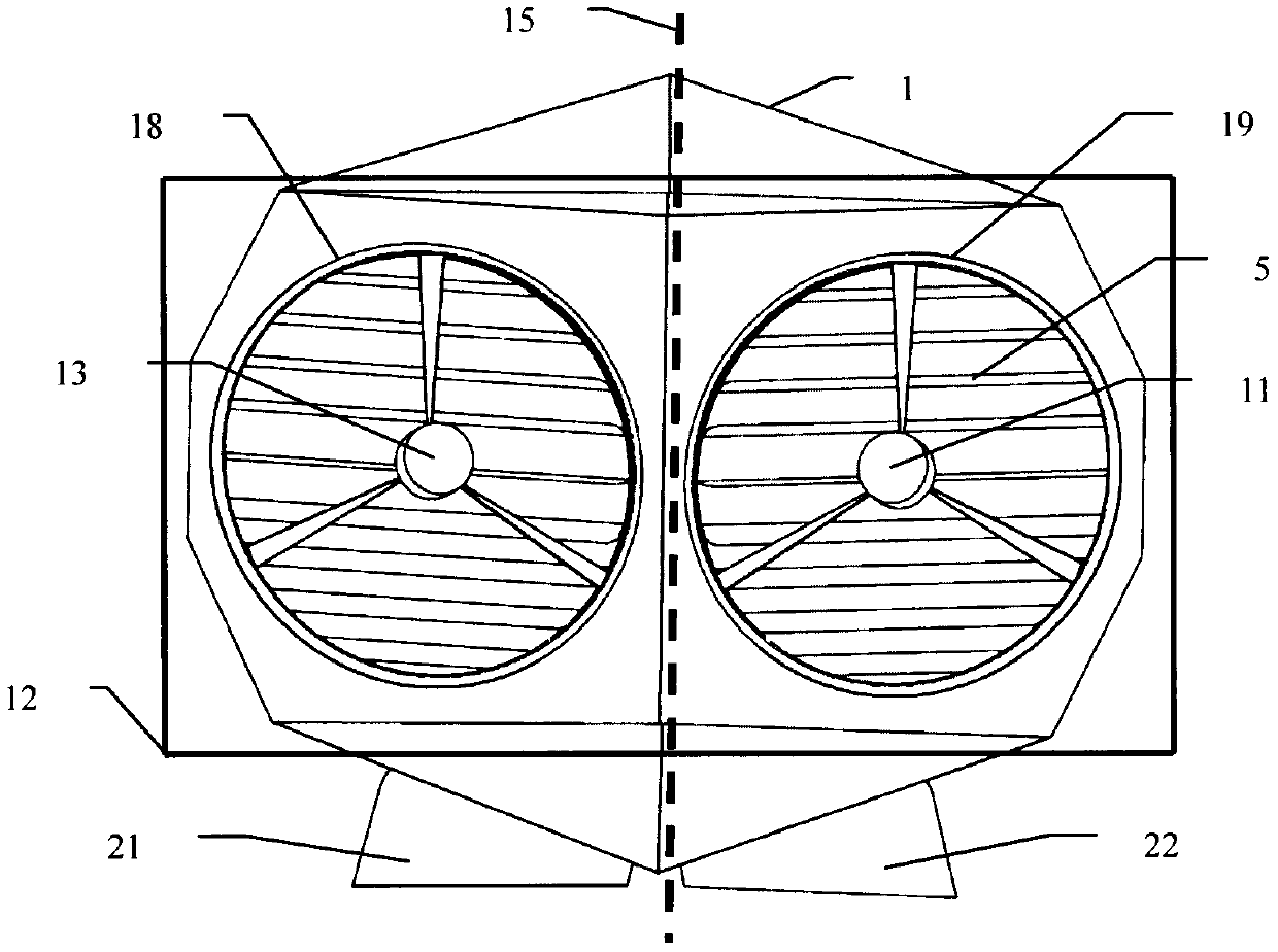
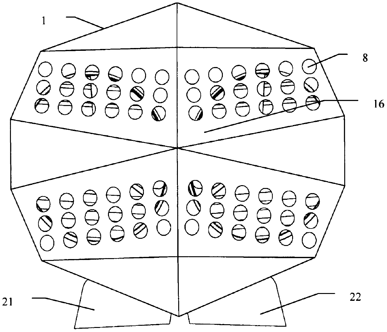
[0040] Such as Figure 1-6 As shown, it includes a body (1), a rotor chamber (2), an air inlet (8), an air outlet (7), a deflector (5), and a rotor (3), wherein the rotor chamber (2) is embedded in the Inside the body (1), the body (1) is provided with the air inlet (8) and the air outlet (7), the air inlet (8), the air outlet (7) and the rotor cavity (2) communicate with each other, the deflector (5) is installed at the air outlet (7), and the rotor (3) is installed in the rotor chamber (2).

[0041] Optionally, the deflector (5) is in the shape of a long thin sheet, and the deflector (5) is provided with a deflector rotation shaft (6), and the deflector (5) can rotate around the The deflector rotating shaft (6) rotates.

[0042] Optionally, a plurality of guide vanes (5) form a guide vane group (4), and the planes of the guide vanes (5) in the same guide vane group...

Embodiment 2

[0062] This embodiment provides an aircraft structure with up and down inner rotors, which is another modified form of the aircraft structure with left and right inner rotors provided in Embodiment 1, and is used to illustrate an inner rotor aircraft provided by the present invention Structural variability.

[0063] Such as Figure 7 As shown, the left and right inner rotors in the rotor chamber described in Embodiment 1 are changed to upper and lower inner rotors, that is, an upper rotor (24) and a lower rotor (25) are provided in the rotor chamber (2), and the The upper rotor (24) and the lower rotor (25) are installed in cascaded form in the rotor cavity (2), the rotation axis of the upper rotor (24), the rotation axis of the lower rotor (25) and the body center The vertical and vertical lines (23) are coaxial, and the rotation plane of the upper rotor (24) and the rotation plane of the lower rotor (25) are parallel to each other. The upper rotor (24) and the lower rotor ...


PUM


Abstract

The invention relates to an aircraft and provides an inner rotor aircraft structure. The inner rotor aircraft structure comprises a structure body, a rotor cavity, an airflow inlet, an airflow outlet,a flow deflector and a rotor. The rotor cavity is inserted into the structure body. The structure body is provided with the airflow inlet and the airflow outlet. The airflow inlet and the airflow outlet are communicated with the rotor cavity. The flow deflector is installed at one or more of the airflow inlet or a position close to the airflow inlet, the airflow outlet or a position close to theairflow outlet, and a position in the rotor cavity. The rotor is installed in the rotor cavity. The inner rotor aircraft structure has a compact structure, realizes stable and flexible flight and suspension control and has a capacity adaptive to a small complicated three-dimensional space.

Description

technical field [0001] The invention relates to the field of aircraft, in particular to an inner rotor aircraft structure. Background technique [0002] Traditional aircraft are generally divided into two categories: fixed-wing and rotary-wing. Fixed-wing aircraft fly fast but most cannot achieve vertical take-off and landing and air suspension. Although rotor aircraft can achieve vertical take-off and landing and air suspension, their flight speed is not high. The rotors of most rotorcraft are exposed, and the flight stability is easily affected by airflow disturbances. The exposed rotors pose a threat to the surrounding environment. In order to increase the lift force, the size of the blades needs to be increased, which cannot meet the miniaturization requirements. Some rotorcraft have added ducts to the rotor. Although it can weaken the influence of airflow disturbance to a certain extent, prevent the rotor from harming the surrounding environment, and reduce the size of ...

Claims


Application Information

Patent Timeline
Patent Type & Authority Applications(China)
IPC IPC(8): B64C27/20B64C27/32
Inventor 袁洪跃
Owner 袁洪跃
Why Eureka
Try Eureka