
Rotary numerical control laser cutting machine for tubular products

A numerical control laser and cutting device technology, applied in auxiliary devices, laser welding equipment, welding/cutting auxiliary equipment, etc., can solve the problems of large damage to the cutting head, difficult to cut completely, difficult to fix, etc., and achieve complete cutting and use range. Wide and labor-saving effect

Pending Publication Date: 2018-01-16
ANHUI UNIV OF SCI & TECH
View PDF7 Cites 5 Cited by
  • Summary
  • Abstract
  • Description
  • Claims
  • Application Information

AI Technical Summary

Problems solved by technology

[0003] Pipe cutting is a part of laser cutting. Most of the pipes are round and not easy to fix when cutting. At the same time, because the diameter of the pipe is larger and the overall thickness is thicker when cutting the pipe, it is difficult to cut the pipe at one time like a plate. It needs constant cutting. Not only the damage to the cutting head is great, but also the efficiency is low

Method used


Image

  • Rotary numerical control laser cutting machine for tubular products
  • Rotary numerical control laser cutting machine for tubular products
  • Rotary numerical control laser cutting machine for tubular products

Examples


Embodiment Construction

[0024] The following description serves to disclose the present invention to enable those skilled in the art to carry out the present invention. The preferred embodiments described below are only examples, and those skilled in the art can devise other obvious variations.

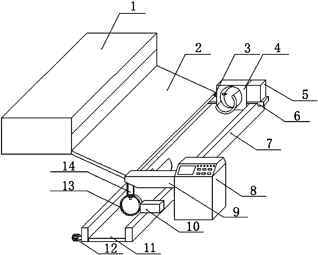
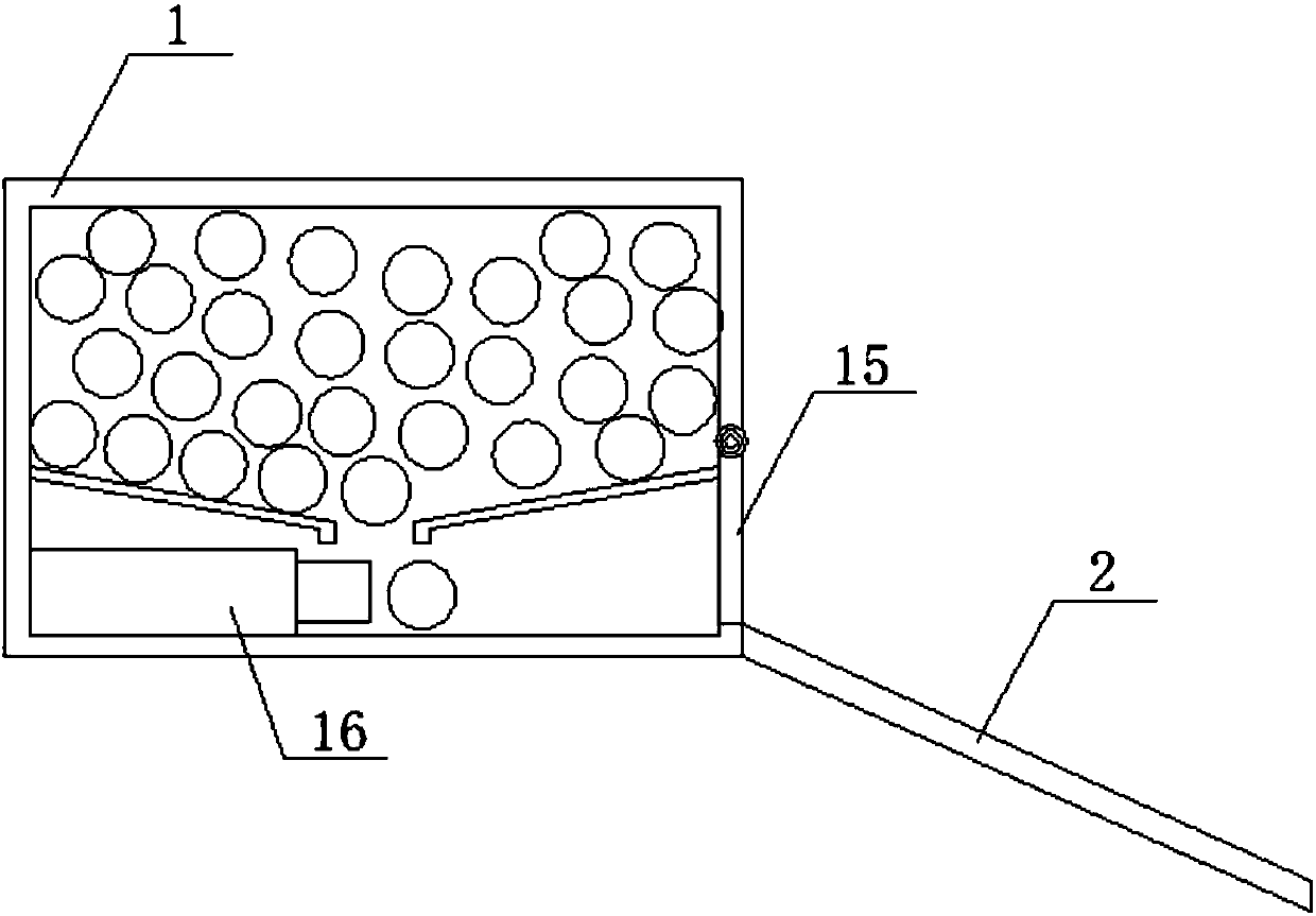
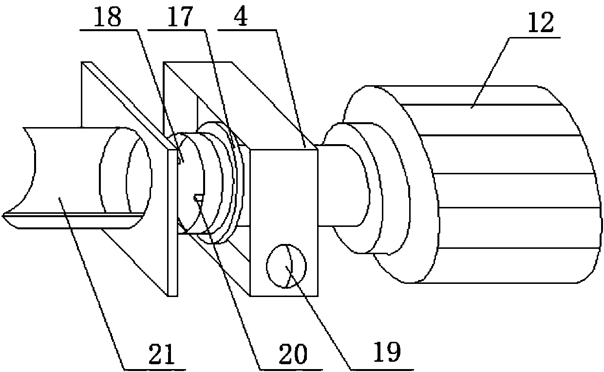
[0025] Please refer to figure 1 , figure 2 , image 3 , Figure 4 Figure 5 ,in, figure 1 A structural schematic diagram of a preferred embodiment of the rotary pipe numerical control laser cutting device provided by the present invention; figure 2 A schematic diagram of the internal structure of the storage box provided by the present invention; image 3 Schematic diagram of the fixed box structure provided by the present invention; Figure 4 Schematic diagram of the structure of the electric control box provided for the present invention; Figure 5 It is a schematic diagram of the connection structure between the dust box and the suspension ring provided by the present invention. A rotary tube n...


PUM


Abstract

The invention provides a rotary numerical control laser cutting machine for tubular products. The rotary numerical control laser cutting machine for tubular products comprises a pneumatic sliding rail, an air cylinder, a fixing box, a supporting plate, a turntable, an electromagnet, a second electric push rod, a motor, an electric control box and a supporting arm, wherein a pneumatic sliding blockis connected to the pneumatic sliding rail in a sliding mode, the air cylinder is connected with the pneumatic sliding block, the fixing box is fixed to the top of the pneumatic sliding block, the supporting plate is connected to the side of the fixing box, the turntable is arranged in the fixing box, the electromagnet is arranged in the turntable, the second electric push rod is fixed to the inner side wall of the turntable, the motor is connected to the turntable, the electric control box is located on the side of the pneumatic sliding rail, the supporting arm is fixed to one side of the electric control box, and the supporting plate is arranged on the side of the supporting arm. Automatic rotation during cutting is effectively achieved, and quick cutting completion is ensured.

Description

technical field [0001] The invention relates to the technical field of cutting, in particular to a rotary pipe numerical control laser cutting device. Background technique [0002] Laser cutting is one of the thermal cutting methods. Compared with other conventional processing methods, laser cutting has greater adaptability and can be adapted to cutting metal or non-metal. It uses a focused high-power density laser beam to irradiate the workpiece to make the workpiece The irradiated material rapidly melts, vaporizes, ablates or reaches the ignition point. At the same time, the molten material is blown away by the high-speed airflow coaxial with the beam, so as to realize the technology of cutting the workpiece. In today's advanced technology, it has a high utilization rate. [0003] Pipe cutting is a part of laser cutting. Most of the pipes are round and not easy to fix when cutting. At the same time, because the diameter of the pipe is larger and the overall thickness is th...

Claims


Application Information

Patent Timeline
Patent Type & Authority Applications(China)
IPC IPC(8): B23K26/362B23K37/053B23Q11/00
Inventor 孙美华杨盼苏国用
Owner ANHUI UNIV OF SCI & TECH
Learn More