
Organic light emitting display panel, display device and manufacturing method thereof

A light-emitting display and panel technology, which is applied in semiconductor/solid-state device manufacturing, semiconductor devices, electrical components, etc., can solve problems such as package failure, inconsistent melting speed, and cracks in packaging materials, so as to improve reliability, uniform melting speed, and reduce The effect of stress

Active Publication Date: 2019-09-24
WUHAN TIANMA MICRO ELECTRONICS CO LTD
View PDF4 Cites 0 Cited by
  • Summary
  • Abstract
  • Description
  • Claims
  • Application Information

AI Technical Summary

Problems solved by technology

When the laser beam is used to melt the glass powder, it is easy to cause the melting speed of the glass powder in the center of the packaging area to be inconsistent with the melting speed of the glass powder at the edge of the packaging area, resulting in stress in the packaging area, which easily causes defects such as cracks in the packaging material. cause package failure

Method used


Image

  • Organic light emitting display panel, display device and manufacturing method thereof
  • Organic light emitting display panel, display device and manufacturing method thereof
  • Organic light emitting display panel, display device and manufacturing method thereof

Examples


Embodiment Construction

[0024] The application will be further described in detail below in conjunction with the accompanying drawings and embodiments. It should be understood that the specific embodiments described here are only used to explain related inventions, not to limit the invention. It should also be noted that, for the convenience of description, only the parts related to the related invention are shown in the drawings.

[0025] It should be noted that, in the case of no conflict, the embodiments in the present application and the features in the embodiments can be combined with each other. The present application will be described in detail below with reference to the accompanying drawings and embodiments.

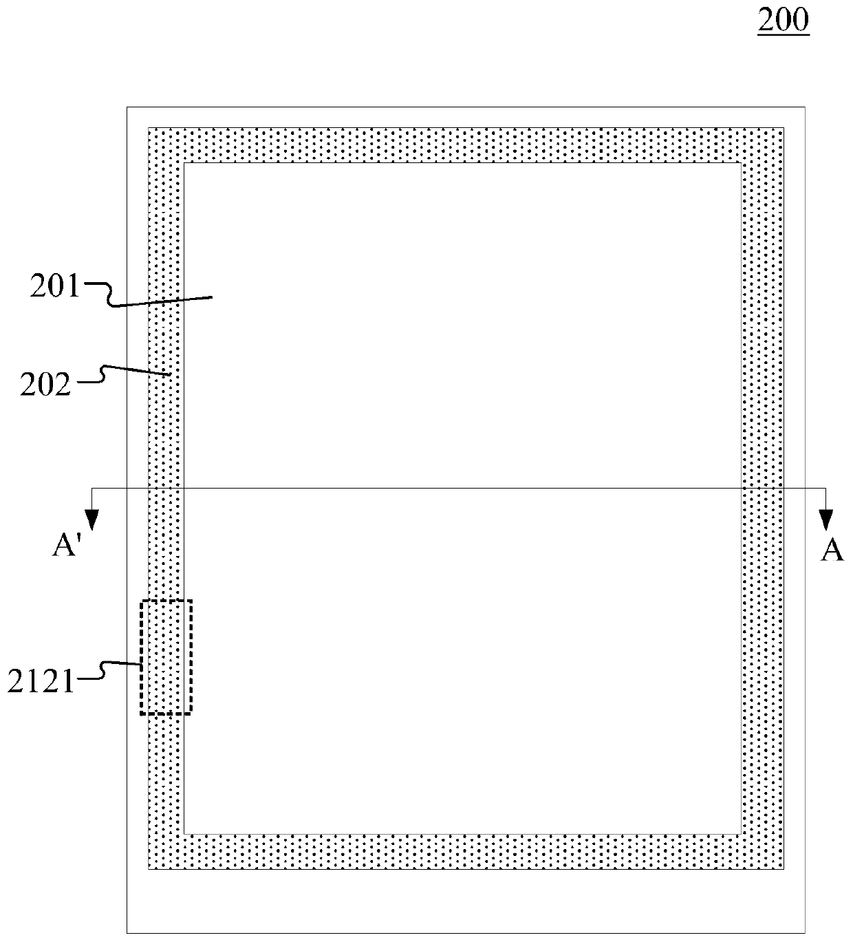
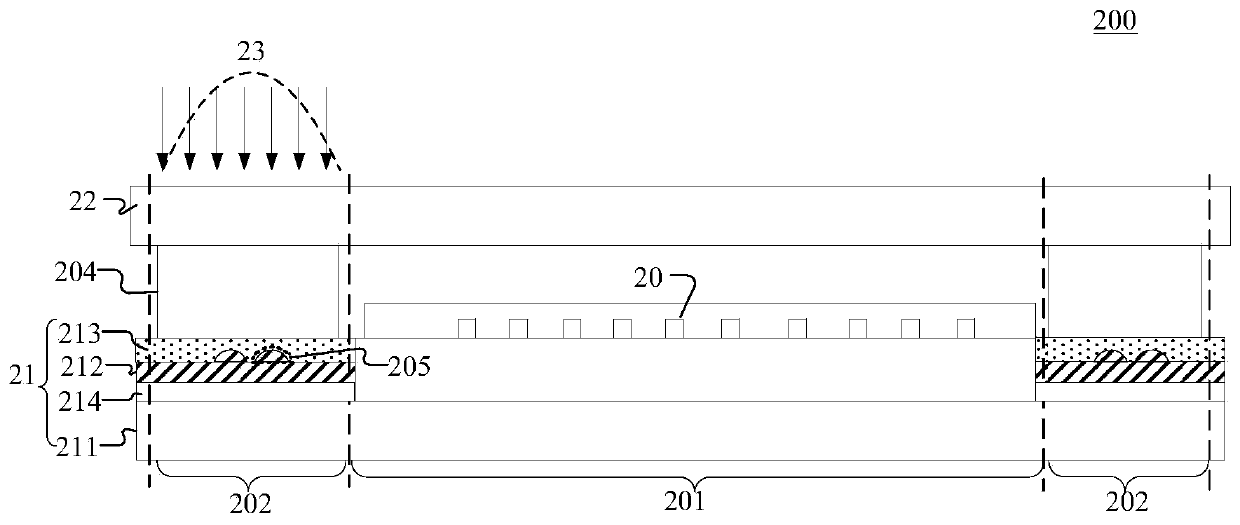
[0026] Please combine figure 2 and image 3 , figure 2 It is a schematic top view structural diagram of an organic light-emitting display panel provided in an embodiment of the present application. image 3 for figure 2 A schematic diagram of the structure of the organic ligh...


PUM


Abstract

The invention discloses an organic light-emitting display panel and a production method thereof and a display device. The organic light-emitting display panel comprises a display area and a packagingarea surrounding the display area; in the display area, multiple organic light-emitting devices are arranged between a substrate and a packaging cover plate, and in the packaging area, a packaging material used for adhering and sealing the substrate and the packaging cover plate is arranged between the substrate and the packaging cover plate; the substrate comprises a substrate body, a metal layerlocated in the packaging area, a first insulation layer located between the metal layer and the packaging material and multiple diffuse reflection protrusions also located between the metal layer andthe packaging material, and particularly, the diffuse reflection protrusions are located on one side of the first insulation layer and away from the packaging cover plate. By the arrangement, energyof laser beam transmission can be evenly distributed in the packaging area, melting rate of glass powder in the center of the packaging area and glass powder at the edge of the packaging area is relatively uniform, stress caused by nonuniform melting rate of the glass powder in the center of the packaging area and the glass powder at the edge of the packaging area can be reduced, and reliability of the organic light-emitting display panel is improved.

Description

technical field [0001] The present application relates to the field of display technology, in particular to an organic light emitting display panel, a display device and a manufacturing method thereof. Background technique [0002] Organic Light Emitting Display (OLED) panels use organic materials that can emit light, and have excellent properties such as ultra-thin, fast response, wide viewing angle, light weight, low power consumption, and high brightness. One of the most promising technologies. [0003] The OLED device itself is very sensitive to water vapor and oxygen, and OLEDs exposed to water vapor and oxygen will have poor working stability and reduced lifespan. Therefore, the packaging of the organic light emitting display panel requires water vapor and oxygen barriers. [0004] One form of packaging for organic light-emitting display panels is cover-type packaging, such as figure 1 The schematic diagram of the encapsulation process between the substrate and the ...

Claims


Application Information

Patent Timeline
Patent Type & Authority Patents(China)
IPC IPC(8): H01L51/52H01L51/56
Inventor 晏国文
Owner WUHAN TIANMA MICRO ELECTRONICS CO LTD
Learn More