Mechanical transmission submerged arc furnace distributing device

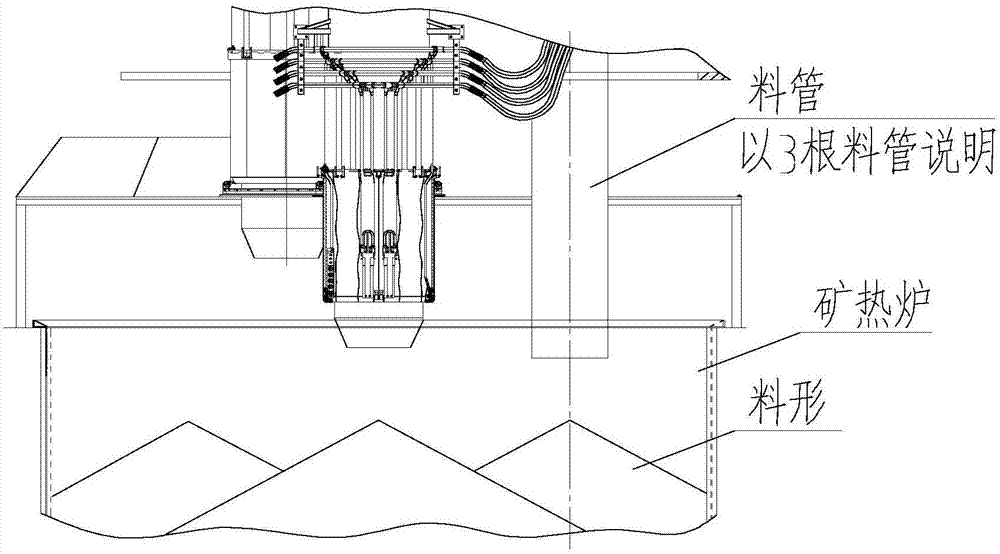
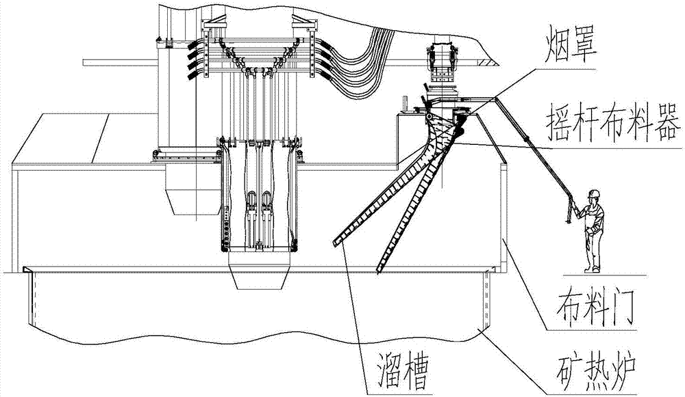
A technology of mechanical transmission and distributor, applied in furnaces, furnace components, lighting and heating equipment, etc., can solve problems such as burning of the head of the material pipe, limited number of material pipes, hidden dangers of accidents, etc., to achieve uniform distribution of materials and reduce power consumption. Energy consumption and the effect of improving economic efficiency

Active Publication Date: 2018-01-12
BERIS ENG & RES CORP
View PDF7 Cites 1 Cited by
  • Summary
  • Abstract
  • Description
  • Claims
  • Application Information

AI Technical Summary

Problems solved by technology

The tube-type feeding method can only be fed at fixed points, and the covering material surface is uneven. In addition, the space of the hood is limited, and the number of tubes to be laid is also limited.
The feeding port of the feeding pipe is mostly water-cooled, and it is also very easy to burst and leak, causing accident hazards and affecting the operation rate of the equipment; burn out
[0003] Although the rocker type feeding can distribute the material to different positions of the submerged arc furnace, the positions of the α angle and β angle of the chute are judged and positioned by the workers based on their experience. The workers first open the material distribution door, visually check the material surface, and manually control the chute by feeling. The α angle (the inclination angle of the distribution chute) and the β angle (the circumferential angle of the distribution chute) are used to realize the distribution. The experience of each worker is different, and the uniformity of the distribution cannot be guaranteed.

Method used


Image

  • Mechanical transmission submerged arc furnace distributing device
  • Mechanical transmission submerged arc furnace distributing device
  • Mechanical transmission submerged arc furnace distributing device

Examples


Embodiment Construction

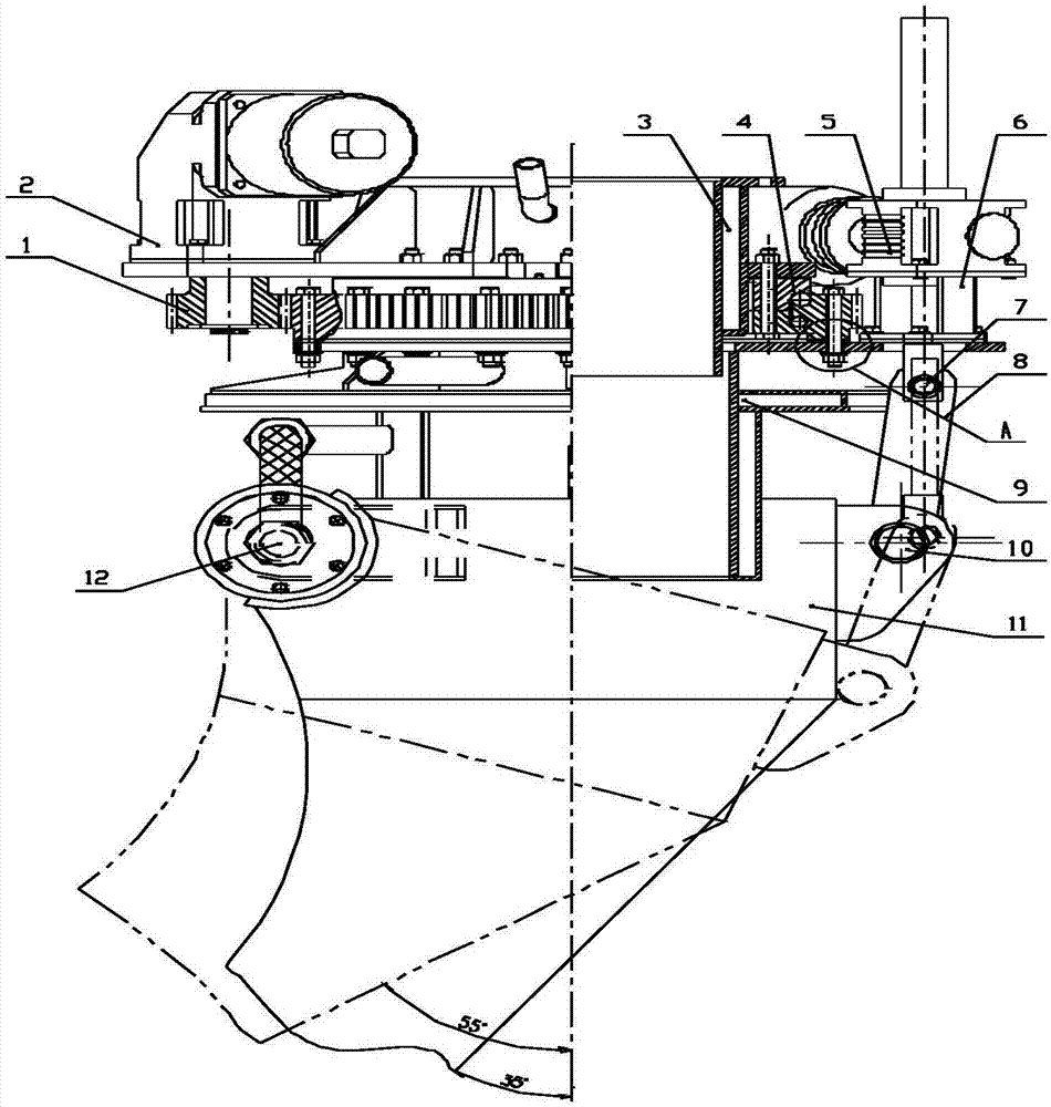
[0019] In order to better understand the purpose, structure and function of the present invention, a mechanically driven submerged arc furnace distributor of the present invention will be further described in detail below in conjunction with the accompanying drawings.

[0020] Such as Figure 3 to Figure 6 As shown, it is shown as a mechanically driven submerged arc furnace distributor of the present invention, including a planetary geared motor 2, a slewing support 4 and a rotary sleeve 9, wherein the planetary geared motor 2 is arranged on the water-cooled central throat pipe 3, and through the bolt Fixed on the steel plate flange in the middle of the water-cooling central throat 3, the output shaft of the planetary gear motor 2 is provided with a pinion 1, and the planetary gear motor 2 drives the pinion 1 to rotate; the slewing support 4 is set on the water-cooling central throat 3, Connect with the steel plate flange in the middle of the water-cooling center throat 3 thro...


PUM


Abstract

The invention discloses a mechanical transmission submerged arc furnace distributing device. The mechanical transmission submerged arc furnace distributing device comprises a planetary gear motor arranged on a water-cooling center throat pipe, a rotation support arranged on the water-cooling center throat pipe, a rotary sleeve connected with the outer ring of the rotation support, and a water-cooling chute, wherein an output shaft of the planetary gear motor is provided with a pinion, and the planetary gear motor drives the pinion to rotate; the inner ring of the rotation support is close to the water-cooling center throat pipe, a gear on the outer ring of the rotation support is engaged with the pinion, and the pinion can drive the rotation support to rotate through the outer ring; the rotary sleeve is connected with the outer ring of the rotation support, and the pinion of the planetary gear motor rotates the rotation support to drive the rotary sleeve to rotate; and the water-cooling chute is connected with the planetary gear motor through a connection rod of a lead screw elevator, and the planetary gear motor drives the water-cooling chute to swing through the connection rod ofthe lead screw elevator. The mechanical transmission submerged arc furnace distributing device can distribute materials onto different ring faces, automatic feeding of any point in a submerged arc furnace is achieved, materials are distributed more evenly, enlargement of the submerged arc furnace is facilitated, and inner consumption of the submerged arc furnace is reduced.

Description

technical field [0001] The invention relates to a submerged arc furnace charging device, in particular to a mechanically driven submerged arc furnace distributor. Background technique [0002] At present, most of the domestic submerged arc furnace feeding equipment is tube type and rocker type (manually operated rocker), such as figure 1 with figure 2 shown. The tube-type feeding method can only be fed at fixed points, and the covering surface is uneven. In addition, the space of the hood is limited, and the number of tubes to be laid is also limited. The discharge port of the feed pipe is mostly water-cooled, and it is also very easy to burst and leak water, causing accident hazards and affecting the operation rate of the equipment; burn out. [0003] Although the rocker type feeding can distribute the material to different positions of the submerged arc furnace, the positions of the α angle and β angle of the chute are judged and positioned by the workers based on exp...

Claims


Application Information

Patent Timeline
Patent Type & Authority Applications(China)
IPC IPC(8): F27B3/18F27D3/10
Inventor 郭飞宇宋春峰张建强
Owner BERIS ENG & RES CORP
Why Eureka
Try Eureka