
Temperature sensing bulb temperature control device

A technology of temperature control device and temperature sensing package, which is applied in the direction of valve device, valve operation/release device, valve lift, etc. It can solve the problems of unsafe use, unreasonable structure, and inability to automatically adjust constant temperature, etc., and achieve convenient operation , Safe to use, simple and understandable structure principle

Inactive Publication Date: 2018-01-12
PINGDINGSHAN ANTAIHUA MINING SAFETY EQUIP MFG
View PDF5 Cites 6 Cited by
  • Summary
  • Abstract
  • Description
  • Claims
  • Application Information

AI Technical Summary

Problems solved by technology

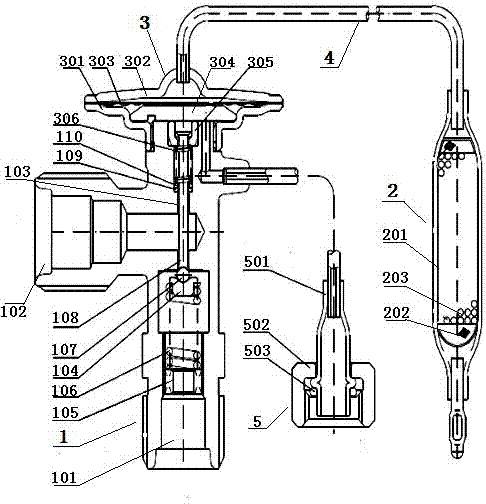
[0004] In order to solve the technical problems such as unreasonable structure of the temperature control device in the existing refrigeration equipment, the inability to automatically adjust the constant temperature, and unsafe use, the present invention provides a temperature control device with a temperature sensing package to achieve a reasonable structure, ingenious design, no Using electricity, it can automatically adjust and maintain a constant temperature, which is safe and convenient to use

Method used


Image

  • Temperature sensing bulb temperature control device

Examples


Embodiment Construction

[0017] The specific implementation manners of the present invention will be further described in detail below in conjunction with the accompanying drawings.

[0018] As shown in the figure, a temperature-sensing package temperature control device includes a hollow air valve 1 and a temperature-sensing package 2 of flexible material communicated with the gas valve 1 through a capillary 4. The temperature-sensing package 2 is filled with an inert gas. The change of gas temperature and volume can adjust the on-off of the refrigerant in the gas valve 1 to achieve temperature regulation. The lower end of the gas valve 1 and one side of the valve body are respectively provided with a first vent 101 and a second vent 101 which communicate with each other. port 102, the upper end of the air valve 1 is provided with a temperature control mechanism 3, and the lower end of the temperature control mechanism 3 is provided with a channel 103 leading to the first vent 101, and a transmission ...


PUM


Abstract

The invention relates to a temperature sensing bulb temperature control device. The temperature sensing bulb temperature control device comprises an air valve and a temperature sensing bulb. The temperature sensing bulb is filled with inert gas. The make-and-break state of refrigerant inside the air valve is adjusted through change of the temperature and volume of the inert gas, so that temperature adjustment is achieved. A temperature control mechanism is arranged at the upper end of the air valve. A valve element bracket is arranged above a first vent hole. A transmission rod pushes a steelball under the effect that the transmission rod is subjected to the gas pressure inside the valve so that the make-and-break state of the first vent hole and a second vent hole can be achieved. A fixing ring is in close contact with the transmission rod through a compression spring. By means of a membrane piece, the gas pressure change inside the temperature sensing bulb is transmitted to a transmission piece, and then, the transmission rod is controlled to move up and down through the compression spring. The temperature sensing bulb temperature control device is reasonable in structure and ingenious in design; the electric power is not used; the constant temperature can be adjusted and maintained automatically; the device is safe and convenient to use; the technical problems that in existing refrigeration equipment, a temperature control device is unreasonable in structure, the constant temperature cannot be adjusted automatically, and the temperature control device is unsafe to use are solved; and for the prior art, the good market prospect and development space are achieved.

Description

technical field [0001] The invention relates to a temperature control device for refrigeration equipment, in particular to a temperature control device for a temperature sensing package. Background technique [0002] Refrigeration equipment is now commonly used in industry, especially in some high-temperature and high-humidity environments. The quality of refrigeration equipment directly affects the health and work efficiency of workers. The temperature control device in traditional refrigeration equipment adopts digital display electronics Control, although the temperature display is clear, but there are the following problems: 1. In coal mines, the use of live equipment will cause electric sparks. When the underground gas concentration is high, it is easy to cause accidents; 2. In some occasions, the temperature control device is required to automatically adjust the temperature to maintain Constant temperature; Third, some temperature control devices have complex structure...

Claims


Application Information

Patent Timeline
IPC IPC(8): F16K31/68F16K1/14
Inventor 范付恒王胜利吴滨强王齐飞
Owner PINGDINGSHAN ANTAIHUA MINING SAFETY EQUIP MFG
Learn More