


Quick Research
Generate reliable direction feasibility study reports for your R&D in just a few steps.

Technical Q&A
Discover and master advanced knowledge NOW. Basics, ideas, possibilities, all at once.

Find Solutions
As an expert in R&D theories, this can generate solutions to your technical problems instantly.

Evaluate Feasibility
Analyze your overall solution with one click, know your potential R&D risks in advance.

Monitor Landscape
Get weekly tech updates, stay abreast of the latest tech innovations and key insights.
Method for evaluating loss of signal link
A signal link and link technology, applied in the computer field, can solve the problem of not knowing the signal insertion loss of the complete link, and achieve the effect of improving product quality and accuracy
- Summary
- Abstract
- Description
- Claims
- Application Information
AI Technical Summary
Problems solved by technology
Method used
Image

Examples
Embodiment 1
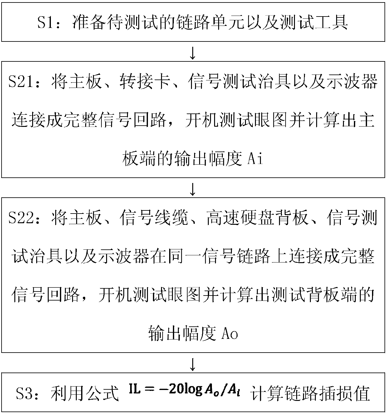
[0028] Such as figure 1 A method for evaluating signal link loss is shown, and the method includes the following steps:
[0029] S1: Prepare the link unit to be tested and test tools. Since this application uses the principle of eye diagram testing to implement, the link unit to be tested includes server motherboards, adapter cards, signal cables, and high-speed hard disk backplanes. Tools include oscilloscope, signal test fixture.
[0030] S2: Measure the output amplitude Ai of the main board and test the output amplitude Ao of the backplane respectively. The specific implementation process is as follows:
[0031] S21: Connect one interface of the adapter card to the SATA port of the motherboard, and then connect the PCIe test tool connected to the oscilloscope to the other interface (hard disk interface) of the adapter card, so that the motherboard, adapter card, signal test tool and oscilloscope are connected Complete the signal loop, turn on the main board, adjust the os...
Embodiment 2
[0043] Such as Figure 5 A method for evaluating signal link loss is shown, and the method includes the following steps:
[0044] S1: Prepare the link unit to be tested and test tools. Since this application uses the principle of eye diagram testing to implement, the link unit to be tested includes server motherboards, adapter cards, signal cables, and high-speed hard disk backplanes. Tools include oscilloscope, signal test fixture.
[0045] S2: Measure the output amplitude Ai of the main board and test the output amplitude Ao of the backplane respectively. The specific implementation process is as follows:
[0046]S21: Connect one interface of the adapter card to the SATA port of the motherboard, and then connect the PCIe test tool connected to the oscilloscope to the other interface (hard disk interface) of the adapter card, so that the motherboard, adapter card, signal test tool and oscilloscope are connected Complete the signal circuit, turn on the main board, adjust the...
PUM
 Abstract
Description
Claims
Application Information
 - R&D Engineer
- R&D Manager
- IP Professional
- Industry Leading Data Capabilities
- Powerful AI technology
- Patent DNA Extraction
Browse by: Latest US Patents, China's latest patents, Technical Efficacy Thesaurus, Application Domain, Technology Topic, Popular Technical Reports.
© 2024 PatSnap. All rights reserved.Legal|Privacy policy|Modern Slavery Act Transparency Statement|Sitemap|About US| Contact US: help@patsnap.com