
Antenna gain test method for satellite navigation user machine based on reference transfer

A technology of satellite navigation and antenna gain, which is applied to satellite radio beacon positioning systems, radio wave measurement systems, measurement devices, etc.

Active Publication Date: 2019-11-22
NO 54 INST OF CHINA ELECTRONICS SCI & TECH GRP
View PDF7 Cites 0 Cited by
  • Summary
  • Abstract
  • Description
  • Claims
  • Application Information

AI Technical Summary

Problems solved by technology

[0004] The purpose of this patent is to solve the influence of the measurement uncertainty of the Beidou user machine antenna gain on the overall machine index test

Method used


Image

  • Antenna gain test method for satellite navigation user machine based on reference transfer

Examples


Embodiment Construction

[0030] The present invention will be further described in detail below in conjunction with the accompanying drawings.

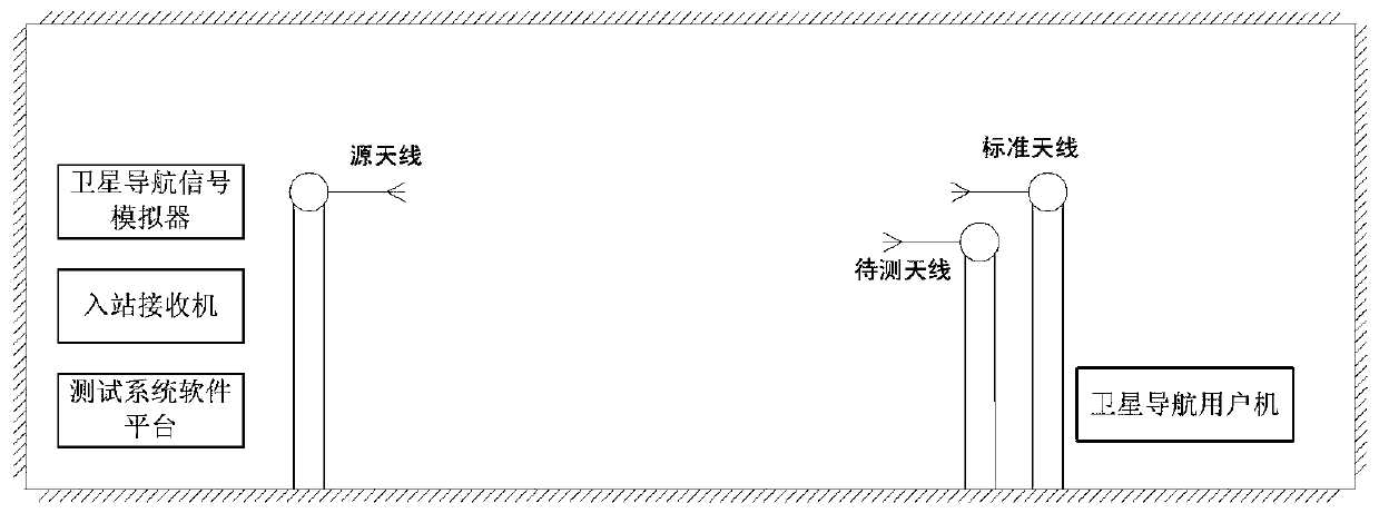
[0031] The schematic diagram of the test system is as follows: figure 1 shown. The essence of the antenna gain testing method of the present invention is to compare the gain of the antenna to be tested with the gain of the known and tested satellite navigation standard antenna to obtain the gain of the antenna to be tested of the Beidou user machine.

[0032] The instruments needed for the whole test method are the satellite navigation signal simulator, the source antenna of the test system, the inbound receiver and the software platform of the test system, the satellite navigation user machine and the tested standard antenna.

[0033] The source antenna is placed at an appropriate height on the test frame, and it is necessary to ensure that the source antenna and the satellite navigation user machine antenna have the same polarization and are aligned with e...


PUM


Abstract

The invention discloses a method for detecting antenna gain of a satellite navigation user receiver by using a satellite navigation user machine test system and using a specially designed satellite navigation standard antenna. To test the satellite navigation user machine antenna, the satellite navigation user machine first uses the calibrated standard antenna, adjusts the outbound signal level of the user machine test system to the sensitivity of the user machine, then removes the standard antenna and replaces it with the antenna to be tested , to test whether the information reported by the satellite navigation user machine to the user machine test system is compared with the information sent by the satellite navigation signal simulator of the test system under the condition of different azimuth and elevation angles and the outbound signal is the sensitivity of the user machine. Indicator requirements such as bit error rate.

Description

technical field [0001] This patent relates to the field of satellite navigation receivers, in particular to a method for detecting the antenna gain of a satellite navigation user machine. [0002] technical background [0003] During the whole machine test process in the software platform of the satellite navigation test system, it is often found that the carrier-to-noise ratio of the satellite navigation receiver is in a critical state when testing the capture sensitivity index, resulting in the performance index of the whole machine not meeting the standard. The cause of the analysis lies in the system error of the test system and the outbound level jitter. The most notable is the influence of the inaccuracy of the antenna gain of the Beidou user machine. Some antenna gain indicators are on the edge of the required indicators, resulting in the carrier-to-noise ratio. Critical state. Contents of the invention [0004] The purpose of this patent is to solve the influence o...

Claims


Application Information

Patent Timeline
Patent Type & Authority Patents(China)
IPC IPC(8): G01S19/23
Inventor 段召亮董建明
Owner NO 54 INST OF CHINA ELECTRONICS SCI & TECH GRP
Learn More