Condenser

A technology for condensers and condensing tubes, applied in steam/steam condensers, tubular elements, heat exchange equipment, etc., which can solve problems such as short flow time, reduced transformer performance, and high temperature, so as to improve flow time and increase Effect of diversion area and low gas temperature

Pending Publication Date: 2018-01-09
重庆新高机电有限公司
View PDF0 Cites 0 Cited by
  • Summary
  • Abstract
  • Description
  • Claims
  • Application Information

AI Technical Summary

Problems solved by technology

[0004] This kind of condenser has a simple structure, the flow time of the material in the condenser is short, the stroke is short, and the area is small, resulting in a poor cooling effect of the material; the material cannot be cooled sufficiently, resulting in a high temperature after the transformer has been running for a long time. The heat cannot be dissipated in time, resulting in a decrease in the performance of the transformer

Method used


Image

  • Condenser
  • Condenser
  • Condenser

Examples


Embodiment 1

[0035] This embodiment provides a condenser.

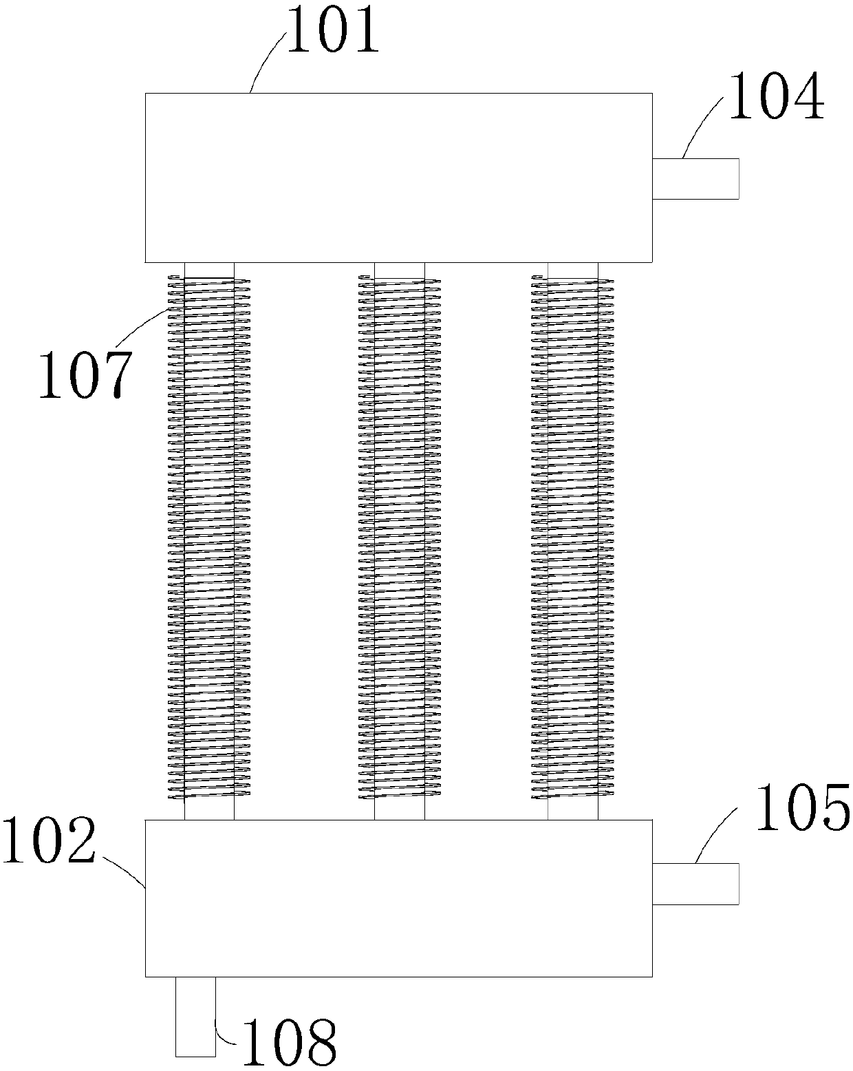
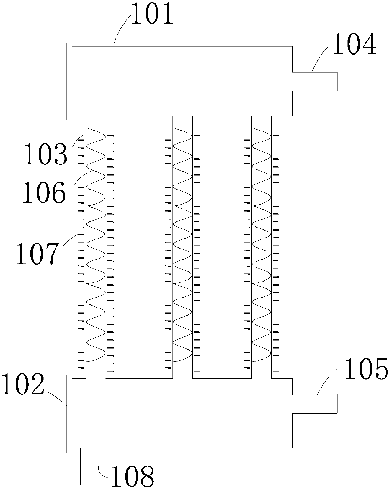
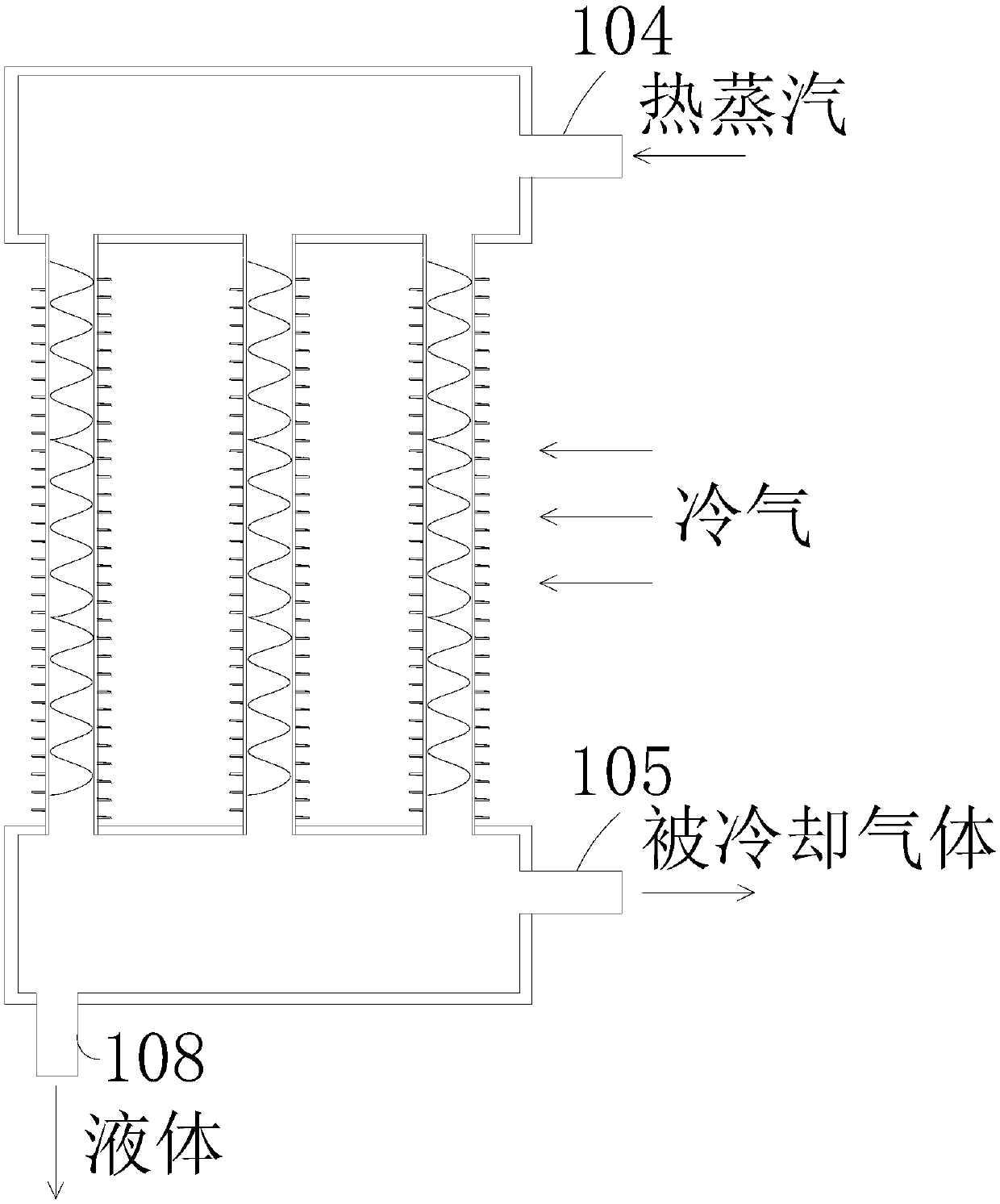
[0036] see figure 1 , this condenser includes an upper shell 101, a lower shell 102 and a condensation pipe 103, the side of the upper shell 101 is connected with an air inlet pipe 104, and the side of the lower shell 102 is connected with an air outlet pipe 105, The bottom of the lower housing 102 is provided with a liquid outflow tube 108 .

[0037] Such as figure 2 As shown, the condensing pipe 103 is connected between the upper housing 101 and the lower housing 102, the condensing pipe 103 is provided with a steel mesh cooling strip 106, and the condensing pipe 103 is provided with a condensing sheet 107, the Both the steel mesh cooling bars 106 and the condensation fins 107 are in a spiral structure and extend along the extension direction of the condensation pipe 103 . The condensing pipes 103 are arranged in parallel; all the condensing pipes 103 are provided with steel mesh cooling strips 106 .

[0038] The steel mesh...


PUM


Abstract

The invention provides a condenser and belongs to the field of transformer oil dehydration and condensing devices in petrochemical engineering. The condenser comprises an upper shell, a lower shell and condensing pipes. The side portion of the upper shell is connected with an air inlet pipe, and the lower shell is connected with an air outlet pipe. The condensing pipes are connected between the upper shell and the lower shell. Steel wire mesh cooling bars of spiral structures are arranged in the condensing pipes correspondingly and extend in the extending direction of the condensing pipes. Byadopting the condenser, the diversion area of hot steam can be increased, the time of flowing of the hot steam in the condensing pipes is prolonged, heat conduction between the hot steam and cold aircan be performed for a longer time, cooling is better conducted, the temperature of cooled air is lower, and a transformer has a better working environment.

Description

technical field [0001] The invention relates to the field of transformer oil dehydration condensing devices in petrochemical industry, in particular to a condenser. Background technique [0002] At present, transformers are often used in petrochemical engineering, and transformers will use condensers for condensation. [0003] The structure of the existing condenser used in the dehydration process of transformer oil is relatively simple. A relatively simple steel pipe is used as the condenser pipe, and the material is passed into the condenser pipe so that the material runs in the condenser pipe; cold air is connected outside the condenser pipe, and the cold wind blows Through the condenser pipe, it can condense the material flowing inside the condenser pipe. [0004] This kind of condenser has a simple structure, the flow time of the material in the condenser is short, the stroke is short, and the area is small, resulting in a poor cooling effect of the material; the mater...

Claims


Application Information

Patent Timeline
Patent Type & Authority Applications(China)
IPC IPC(8): F28B1/06F28F1/42F28F1/44
Inventor 穆朋肖孝强万林肖世成冯伟石庆刚
Owner 重庆新高机电有限公司
Why Eureka
Try Eureka