Die-cutting device and die cutter applying same
A die-cutting and rotating roller technology, applied in metal processing and other directions, can solve problems such as increasing production costs, achieve the effects of easy operation, avoid frequent replacement of rotating rollers, and reduce production costs
- Summary
- Abstract
- Description
- Claims
- Application Information
AI Technical Summary
Problems solved by technology
Method used
Image

Examples
Embodiment 1
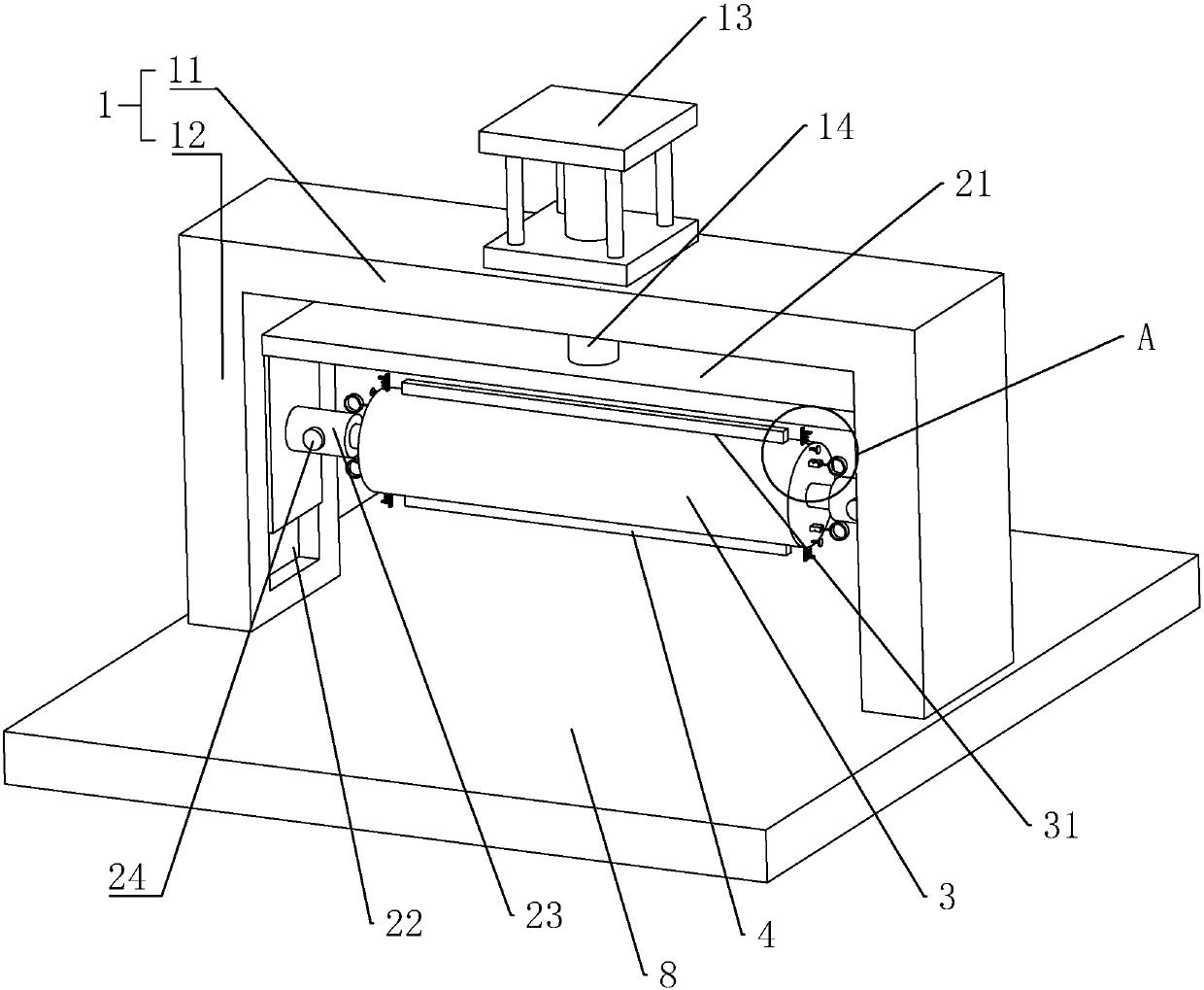
[0038] Embodiment 1: a kind of die-cutting device, as Figure 1 to Figure 3 As shown, including a support frame 1, the support frame 1 is composed of two vertical bars 12 and a cross bar 11, the upper ends of the two vertical bars 12 are fixedly connected with the two ends of the cross bar 11, and the long side direction of the cross bar 11 is along the horizontal Direction is set, and the longitudinal direction of vertical bar 12 is set along vertical direction. Both the cross bar 11 and the vertical bar 12 are arranged in a cuboid shape.
[0039] A hydraulic cylinder 13 is fixed on the side of the cross bar 11 facing away from the vertical bar 12, and the hydraulic shaft of the pneumatic cylinder is fixedly connected through the cross bar 11 and the support 21; The guide groove 22 is arranged along the vertical direction, and the bracket 21 is placed in the guide groove 22 and moves up and down along the guide groove 22 .
[0040] A sleeve 23 is arranged on both sides of t...
Embodiment 2
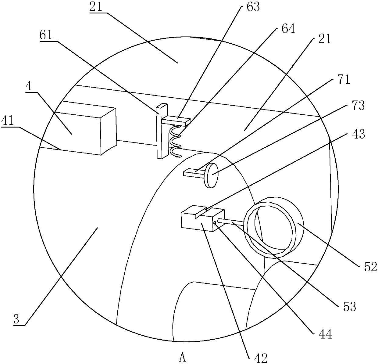
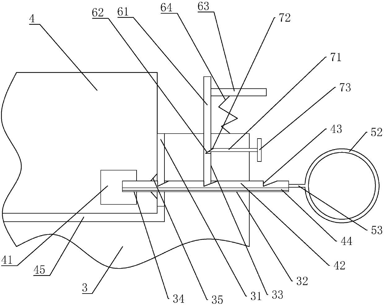
[0048] Embodiment 2: a kind of die-cutting device, as Figure 4 to Figure 6 As shown, the difference with Embodiment 1 is that the setting of the drive rod 71 is eliminated (see image 3 ).
[0049] The limit block 61 is hinged to the end of the rotating roller 3 through the connecting shaft 51 . The distance between the end of the limit block 61 away from the sliding part 42 and the connecting shaft 51 is far greater than the distance between the connecting shaft 51 and the sliding part 42, and the two ends of the elastic part 64 are respectively connected to the end of the limit block 61 and the rotating roller 3. Fixed connection.
[0050] During use, as described in Embodiment 1, the sliding member 42 moves along the chute 32 toward the direction of the cutting and pressing member 4, and the sliding member 42 is placed in the limiting hole 34, and is aligned with the limiting hole 34. The inner wall is in conflict, and at the same time, through the elastic force of the ...
Embodiment 3
[0051] Embodiment 3: a kind of die-cutting machine, as figure 1 , Figure 4 and Figure 7 As shown, it includes a die-cutting machine body 9 and a die-cutting device as described in Embodiment 1 or Embodiment 2. The die-cutting device is placed in the die-cutting machine body 9, and the paper enters from one end of the die-cutting machine body 9, Placed on the workbench 8, the piston shaft 14 on the hydraulic cylinder 13 pushes the bracket 21 to move down along the guide groove 22, so that the cutting piece 4 can cut the paper. After cutting, the piston shaft 14 pulls the bracket 21 to reset, Then the paper is passed out from the other end of the die-cutting machine body 9 to complete the die-cutting process.
[0052] By rotating the rotating shaft, another cutting and pressing member 4 can be used to cut the paper, eliminating the cumbersome process of replacing the cutting and pressing member 4, and improving production efficiency. When it is necessary to install the cutti...
PUM
 Abstract
Description
Claims
Application Information
 - R&D
- Intellectual Property
- Life Sciences
- Materials
- Tech Scout
- Unparalleled Data Quality
- Higher Quality Content
- 60% Fewer Hallucinations
Browse by: Latest US Patents, China's latest patents, Technical Efficacy Thesaurus, Application Domain, Technology Topic, Popular Technical Reports.
© 2025 PatSnap. All rights reserved.Legal|Privacy policy|Modern Slavery Act Transparency Statement|Sitemap|About US| Contact US: help@patsnap.com