Punch for binding
A technology of hole puncher and mounting plate, applied in the field of hole puncher, can solve the problems of no automatic centering, hole punching dislocation, etc.
- Summary
- Abstract
- Description
- Claims
- Application Information
AI Technical Summary
Problems solved by technology
Method used
Image
Examples
Embodiment 1
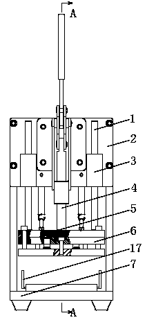
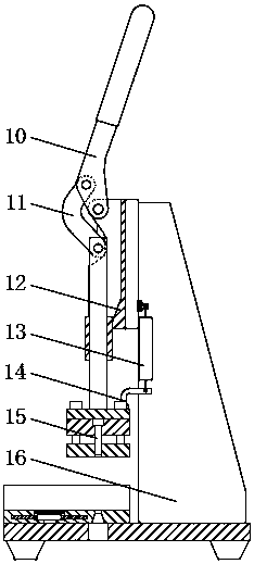
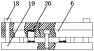
[0023] combined with Figure 1-4 As shown, a hole puncher for binding includes a vertical plate 2 arranged in sequence from top to bottom, a cover plate 5 slidingly connected up and down with the vertical plate 2, a tool fixing plate 6 fixedly connected with the cover plate 5, and a clamp 17. The bottom plate 7 connected with the fixture 17; the vertical plate 2 is provided with a driving device for driving the cover plate 5 to slide; the knife fixing plate 6 is pierced with a punching knife 15; the knife fixing plate 6 and the fixture 17 are provided There is a binder plate 19; a first spring 20 is arranged between the binder plate 19 and the cover plate 5, and the upper end surface of the binder plate 19 is connected with a T-shaped equal-height connector 18; the lower end surface of the large end of the equal-height connector 18 The drive device includes a base 12 fixedly connected to the vertical plate 2, a handle 10 hingedly connected to the base 12, a handle 10 slidably ...
Embodiment 2
[0025] For implementing the present invention better, on the basis of embodiment 1, in conjunction with appended Figure 1-4 As shown, further, a second spring 13 is connected between the vertical plate 2 and the cover plate 5 .
[0026] working principle:
[0027] Such as figure 2 As shown, the vertical plate 2 is connected with the bottom plate 7 through the reinforcing rib 16, so as to increase the space for placing paper; one end of the second spring 13 is connected with the cover plate through the spring connector 14, and the other end of the second spring 13 is passed through Another spring connector 14 is connected with the vertical plate 2 . figure 2 is the initial state of the device, when using the device, such as Figure 1-4 As shown, firstly the first baffle 171 is pulled to the left or the second baffle 173 is pulled to the right, and then the other baffle moves automatically under the drive of the gear 172 . For example, when the first baffle 171 is pulled to...
Embodiment 3
[0029] For implementing the present invention better, on the basis of embodiment 1, in conjunction with appended Figure 1-4 As shown, further, a bushing 3 is fixedly connected to the vertical plate 2 , and a guide rod 1 connected to the cover plate 5 is pierced through the bushing 3 .
PUM
 Abstract
Description
Claims
Application Information
 - R&D Engineer
- R&D Manager
- IP Professional
- Industry Leading Data Capabilities
- Powerful AI technology
- Patent DNA Extraction
Browse by: Latest US Patents, China's latest patents, Technical Efficacy Thesaurus, Application Domain, Technology Topic, Popular Technical Reports.
© 2024 PatSnap. All rights reserved.Legal|Privacy policy|Modern Slavery Act Transparency Statement|Sitemap|About US| Contact US: help@patsnap.com


