
Grinding and polishing robot clamp system capable of being switched between 0-degree working state and 90-degree working state and using method thereof

A technology for robot fixtures and switching work, which is applied in the direction of grinding workpiece supports, etc., to achieve the effects of flexible and intelligent movement, shortening the process flow, and reducing the equipment footprint

Pending Publication Date: 2018-01-09
广东博科数控机械有限公司
View PDF5 Cites 5 Cited by
  • Summary
  • Abstract
  • Description
  • Claims
  • Application Information

AI Technical Summary

Problems solved by technology

[0004] However, there are no specific records in this regard in some prior patent documents disclosed in related fields at present. The information of these related prior documents is as follows: 1. A robot fixture with the authorized announcement number CN203779505U; 2. The application number is CN201510212269. 0; 3. The application number is CN201520758303.X, a versatile robot gripper; 4. The application number is CN201520895499.7, a flexible robot gripper; 5. An automatic positioning robot fixture with application number CN201620328095.4

Method used


Image

  • Grinding and polishing robot clamp system capable of being switched between 0-degree working state and 90-degree working state and using method thereof
  • Grinding and polishing robot clamp system capable of being switched between 0-degree working state and 90-degree working state and using method thereof
  • Grinding and polishing robot clamp system capable of being switched between 0-degree working state and 90-degree working state and using method thereof

Examples


Embodiment Construction

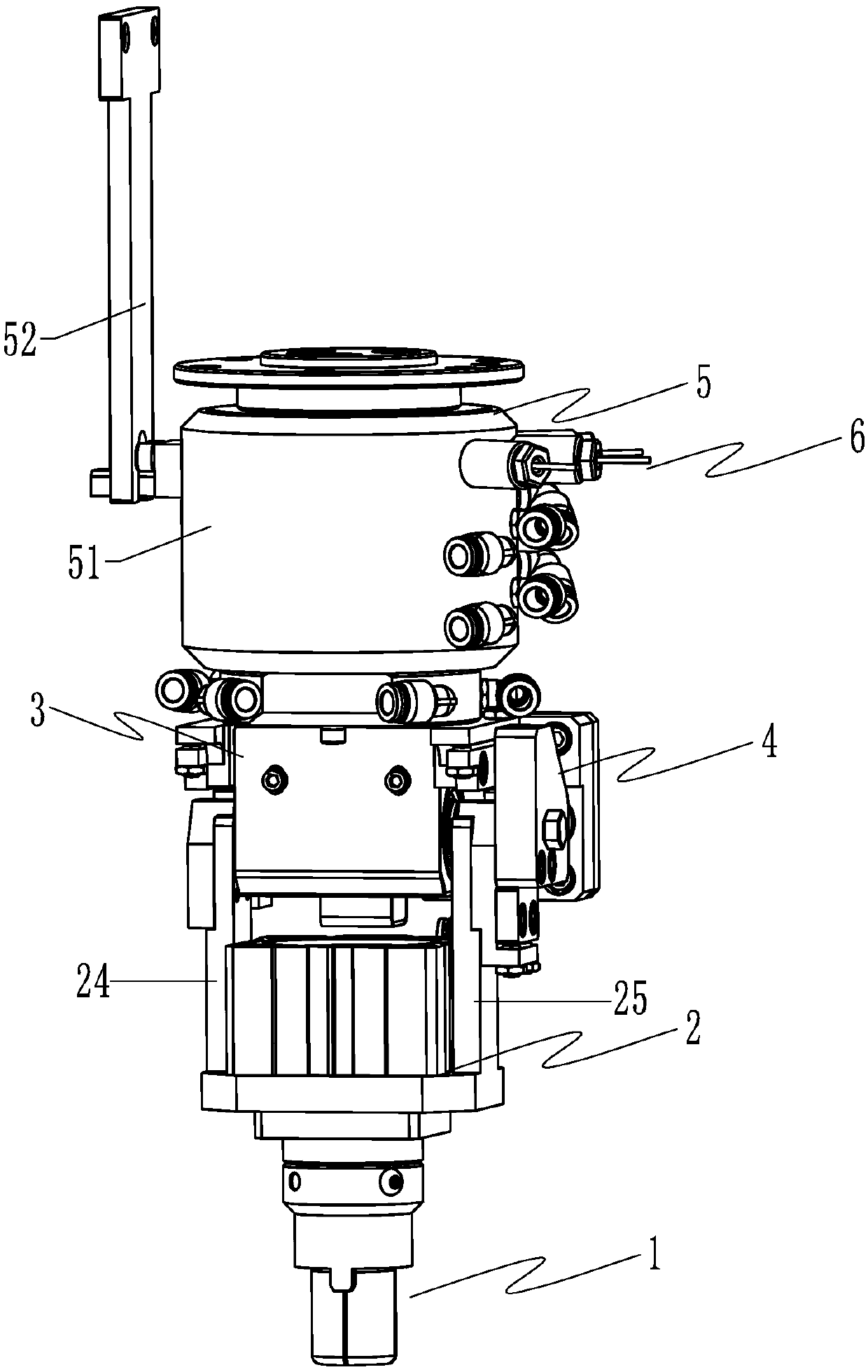
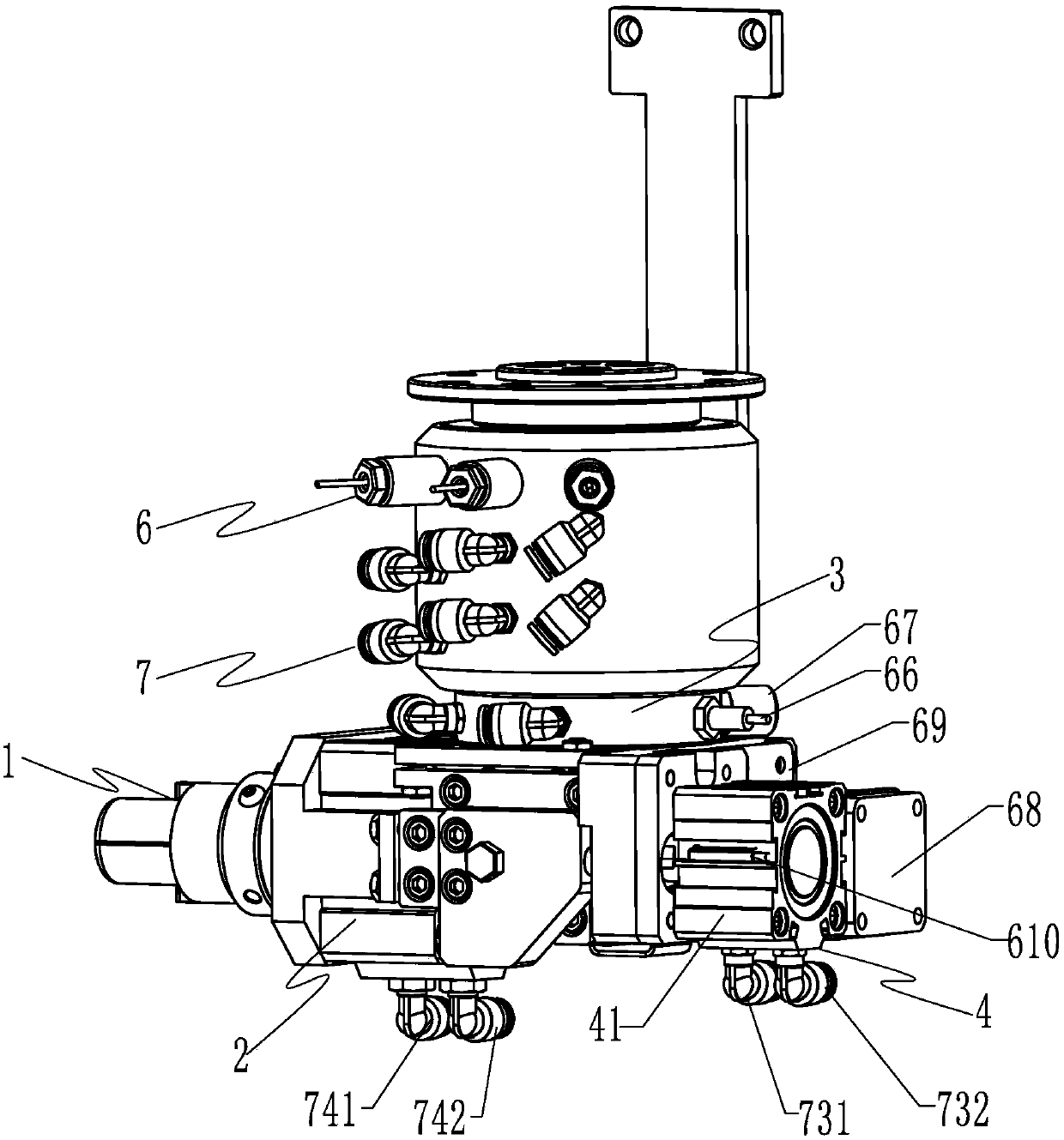
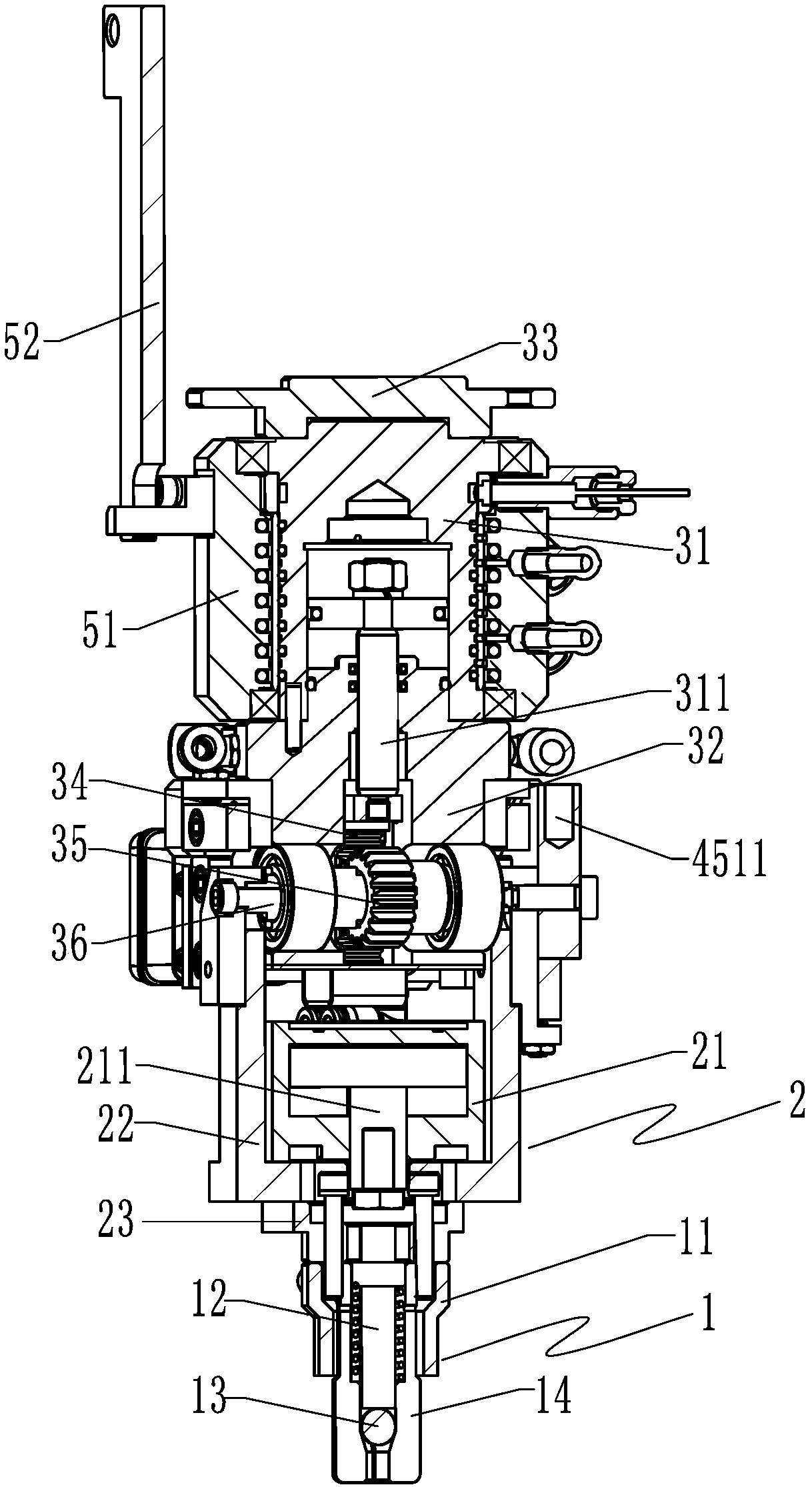
[0034] like Figures 1 to 9 As shown, a grinding and polishing robot fixture system with two switching working states of 0 degrees and 90 degrees according to the present invention includes a fixture head assembly 1 and a tightening drive that is tightly connected with the fixture head to drive the fixture head assembly to work. Assembly 2. Rotary drive assembly 3 for driving and controlling the overall switching of the tensioning drive assembly and the fixture head assembly in two working states of 0° and 90°, and a positioning drive for restricting the overall positioning of the tensioning drive assembly and the clamp head assembly Component 4.

[0035] like figure 1 , 3 As shown, the clamp head assembly 1 includes a clamp head sleeve 11, a push rod body 12 installed in the clamp head sleeve, a push steel ball 13 and a spring chuck 14; the tightening drive assembly 2 includes There is a tensioning cylinder 21 and a tensioning connection seat 22, wherein: one end of the te...


PUM


Abstract

The invention discloses a grinding and polishing robot clamp system capable of being switched between a 0-degree working state and a 90-degree working state. The grinding and polishing robot clamp system comprises a clamp head assembly, a tensioning driving assembly, a rotating driving assembly and a positioning driving assembly, wherein the tensioning driving assembly is in fastened connection with a clamp head so as to drive to clamp head assembly to work, the rotating driving assembly is used for driving and controlling the tensioning driving assembly and the clamp head driving assembly tobe overall switched between the 0-degree working state and the 90-degree working state, and the positioning driving assembly is used for limiting the tensioning driving assembly and the clamp head driving assembly for overall positioning. The rotating driving assembly adopts a transmission structure operating in the mode that a rotating air cylinder drives a rack to drive a gear. The positioning driving assembly adopts a positioning structure operating in the mode that a positioning air cylinder drives a bolt to be inserted into an inserting hole. The overall structure is simpler and more compact, and operation is easier, more convenient and rapider; the grinding and polishing robot clamp system adapts to grinding and polishing of multiple complex workpieces, the probability of manual operation for repairing is decreased, and standardized production is facilitated; and the production efficiency and the surface quality of a grinded and polished workpiece are improved.

Description

technical field [0001] The invention relates to a grinding and polishing robot, belonging to the technical field of polishing robot equipment, in particular to a grinding and polishing robot fixture system with two switching working states of 0° and 90° and a method of using the same. Background technique [0002] At present, the grinding and polishing mechanical equipment makes full use of the intelligence and flexibility of the robot. The end effector of the robot is used to install the fixture head assembly that matches the workpiece, and the grinding and polishing process of the continuous workpiece of various shapes and curved surfaces can be completed. However, due to the tight connection between the fixture head assembly and the robot end effector, the center lines of the two remain unchanged, resulting in some local areas of many complex workpieces still unable to be processed and still need to be repaired manually, thus reducing the scope of application of the equipm...

Claims


Application Information

Patent Timeline
Patent Type & Authority Applications(China)
IPC IPC(8): B24B41/06
CPCY02P70/10
Inventor 梁志强黄溢明梁雄基赵照洪
Owner 广东博科数控机械有限公司
Learn More