Clamping mechanism for centrifugal microfluidics CD chip

A clamping mechanism and microfluidic technology, used in laboratory containers, laboratory utensils, supporting utensils, etc.

Active Publication Date: 2018-01-09
NORTHWESTERN POLYTECHNICAL UNIV
View PDF4 Cites 2 Cited by
  • Summary
  • Abstract
  • Description
  • Claims
  • Application Information

AI Technical Summary

Problems solved by technology

[0004] The purpose of the present invention is to provide a convenient, quick and reliable CD-type chip clamping mechanism for the defects of the existing centrifugal microfluidic chip clamping and fixing mechanism

Method used


Image

  • Clamping mechanism for centrifugal microfluidics CD chip
  • Clamping mechanism for centrifugal microfluidics CD chip
  • Clamping mechanism for centrifugal microfluidics CD chip

Examples


Embodiment Construction

[0014] The specific content of the present invention is further described in detail below in conjunction with the embodiment shown in the accompanying drawings:

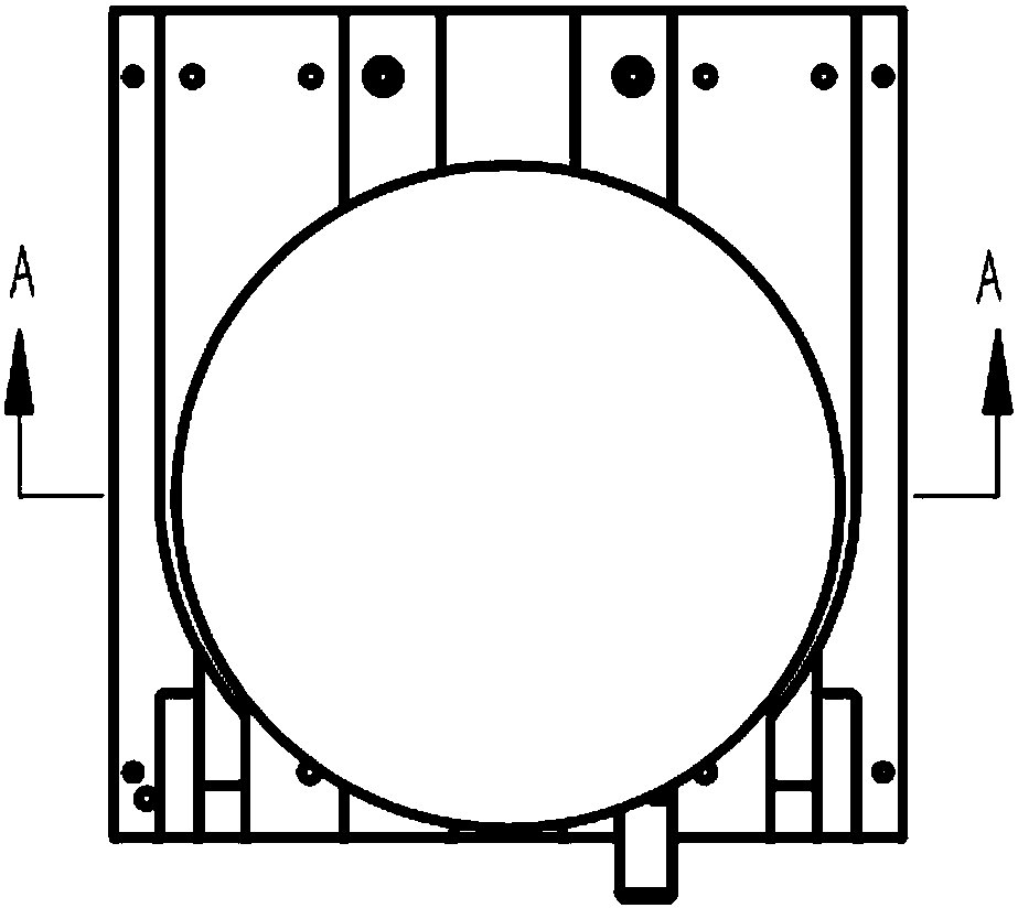
[0015] refer to figure 1 , The present invention includes: a chip bracket 1, a guide groove 7, a guide block 6, a lever 2, a push rod 3, a positioning marble 4, and a motor shaft slot 5.

[0016] Chip radius r=30mm, thickness d=5mm, PC material, processed by Jingdiao machine tool. The radius of the chip positioning block and the motor card slot is 10mm, the chip positioning block and the chip are bonded together by shadowless glue, and the motor card slot and the motor shaft are fixed by screws. Position the marbles with a radius of 2mm and polish them. The chip bracket is made of plexiglass material, and the chip bracket is selected according to the size of the chip to leave a 10mm gap on both sides to prevent the chip from colliding with the bracket.

[0017] When using, firstly connect the motor card slot and t...


PUM


Abstract

The invention belongs to the microfluidics field and discloses a clamping mechanism for a centrifugal microfluidics CD chip. The mechanism comprises chip support racks 1, a lever 2, a push rod 3, a positioning marble 4, a motor shaft clamping groove 5, a guide block 6 and a guide slot 7. The chip is inserted to the bottom along the guide slot 7 and can reach the accurate position by means of the horizontal positioning function of the guide block 6 and cooperation with the motor shaft clamping groove 5, and the chip is completely positioned when the positioning marble 4 in the motor shaft clamping groove 5 bounces; when the chip is required to be taken out, all that is required is to push the push rod 3 and the chip can automatically bounce under the action of the lever 2. The distance between the chip support racks 1 can be conveniently adjusted and thus the mechanism can adapt to chips with different sizes. The clamping mechanism for the centrifugal microfluidics CD chip is designed in the CD driver principle, can conveniently clamp and position the chip and has the advantages of being simple in structure, convenient to operate, reliable and high in adaptability.

Description

technical field [0001] The invention relates to a new mechanism in the field of clamping and fixing centrifugal microfluidic chips. Specifically, the invention provides a CD-type chip clamping mechanism for centrifugal microfluidics. technical background [0002] Microfluidic Analysis is the main component of a miniature total analysis system, and the Microfluidics Chip, which integrates various functions of chemical analysis on a postage stamp-sized chip, is currently the most active development frontier. , representing the development direction of miniaturization and integration of analytical instruments in the 21st century, has become the goal of many famous laboratories at home and abroad. [0003] Centrifugal microfluidic chips do not require complicated peripheral driving equipment, and can control the driving force only by adjusting the speed, and are not constrained by the gravity of the earth, so they have great advantages. However, there has been no convenient, fa...

Claims


Application Information

Patent Timeline
IPC IPC(8): B01L9/00B01L3/00
Inventor 苑伟政何洋吕湘连周兴攀曹小宝卢宇超王圣坤杨儒元常洪龙
Owner NORTHWESTERN POLYTECHNICAL UNIV
Why Eureka
Try Eureka