Artificial skin based on piezoelectric material and thermistor material and detection method of artificial skin
A technology of thermistors and piezoelectric materials, applied in thermometers that are directly sensitive to heat/magnetic elements, measurement of properties and forces using piezoelectric devices, and measurement devices, etc., can solve the problem that artificial skin does not have intelligent detection function, difficult to expand to a large area, and low detection sensitivity
- Summary
- Abstract
- Description
- Claims
- Application Information
AI Technical Summary
Problems solved by technology
Method used
Image
Examples
Embodiment 1
[0125] Example 1 An artificial intelligence skin based on piezoelectric materials and thermistor materials
[0126] This embodiment is a mechanical arm of a telemedicine machine, which is provided with an artificial intelligence skin based on piezoelectric material and thermistor material, and the skin includes a signal acquisition part and a circuit part;
[0127] 1) Signal acquisition part
[0128] The signal acquisition part includes a device protection layer 1 and a composite signal acquisition layer disposed under the device protection layer 1;
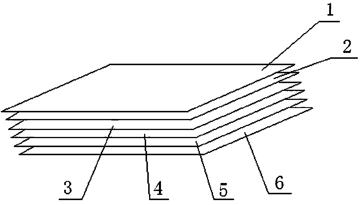
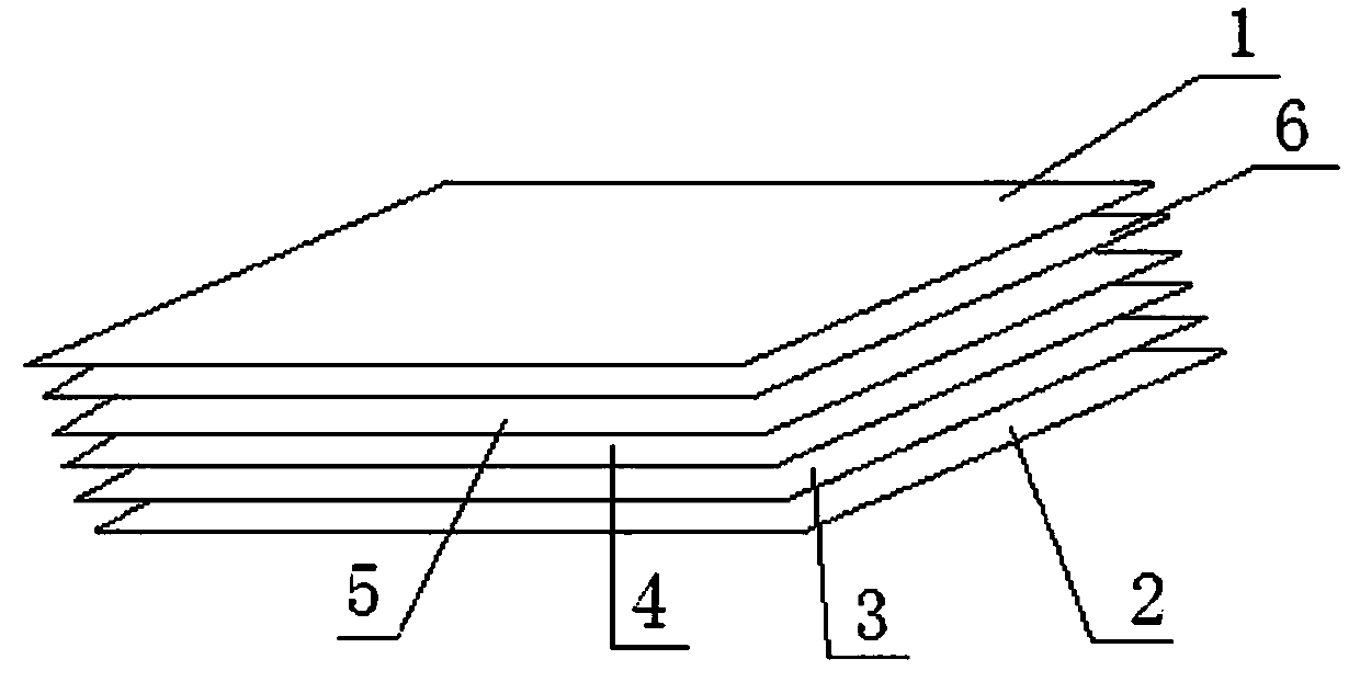
[0129] refer to figure 1 , the composite signal acquisition layer is composed of a first electrode layer 2, a thermistor material layer 3, a second electrode layer 4, a piezoelectric material layer 5 and a third electrode layer 6 arranged sequentially from top to bottom;
[0130] The first electrode layer 2, the thermistor material layer 3 and the second electrode layer 4 together form a temperature detection layer, and the sec...
Embodiment 2
[0141] Embodiment 2 A kind of artificial intelligence skin
[0142] In this embodiment, on the basis of the artificial intelligence skin in Embodiment 1, the back-end circuit is further optimized, refer to Figure 5 ,exist image 3 On the basis of the back-end circuit also includes a second controller, a second multiplexer and a first excitation electrode layer; the signal output end of the first central processing unit is connected with the signal input end of the second controller, and the second controller The control signal output end of the first excitation electrode layer is connected to the signal input end of the first excitation electrode layer through the second multiplexer, the first excitation electrode layer includes N3 small excitation electrode layer units, the said N3≥1, and N3 is N1, N2 the maximum of both.
[0143] refer to Image 6 ,exist Figure 4 On the basis of the second structure, the back-end circuit of the second structure also includes a third co...
Embodiment 3
[0145] Example 3 A method for detecting pressure and temperature
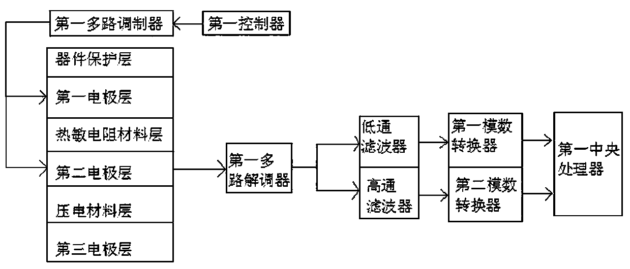
[0146] This embodiment adopts embodiment 1 to realize, when adopting image 3 In the case of the back-end circuit, the method is method one, which includes the following steps in sequence:
[0147] 1. Output a DC voltage / current signal to the first multiplexer through the first controller, and the first multiplexer modulates the received DC voltage / current signal and outputs it to the first electrode layer 2 and the second Electrode layer 4;
[0148] When the robotic arm touches the patient's body, it is assumed that the part of the robotic arm that touches the patient's body corresponds to the Mth (1≤M≤N1) small electrode of the first electrode layer 2 and the Sth ( 1≤S≤N2) small electrodes. At this time, the temperature of the outer surface of the mechanical arm corresponding to the Mth small electrode of the first electrode layer 2 changes, and the resistivity of the thermistor material layer 3 changes. Th...
PUM
 Abstract
Description
Claims
Application Information
 - R&D
- Intellectual Property
- Life Sciences
- Materials
- Tech Scout
- Unparalleled Data Quality
- Higher Quality Content
- 60% Fewer Hallucinations
Browse by: Latest US Patents, China's latest patents, Technical Efficacy Thesaurus, Application Domain, Technology Topic, Popular Technical Reports.
© 2025 PatSnap. All rights reserved.Legal|Privacy policy|Modern Slavery Act Transparency Statement|Sitemap|About US| Contact US: help@patsnap.com


