Projection imaging correction method and apparatus, and laser TV

A correction method and projection technology, applied in the field of image processing, can solve difficult, time-consuming and cumbersome problems

Active Publication Date: 2018-01-05
上海顺久电子科技有限公司
View PDF6 Cites 28 Cited by
  • Summary
  • Abstract
  • Description
  • Claims
  • Application Information

AI Technical Summary

Problems solved by technology

For professional debuggers, accurate alignment is a relatively time-consuming and cumbersome process, and for ordinary users who are not familiar with projection equipment, it is even more difficult.

Method used


Image

  • Projection imaging correction method and apparatus, and laser TV
  • Projection imaging correction method and apparatus, and laser TV
  • Projection imaging correction method and apparatus, and laser TV

Examples


Embodiment Construction

[0053] In order to make the above objects, features and advantages of the present application more obvious and comprehensible, the present application will be further described in detail below in conjunction with the accompanying drawings and specific implementation methods.

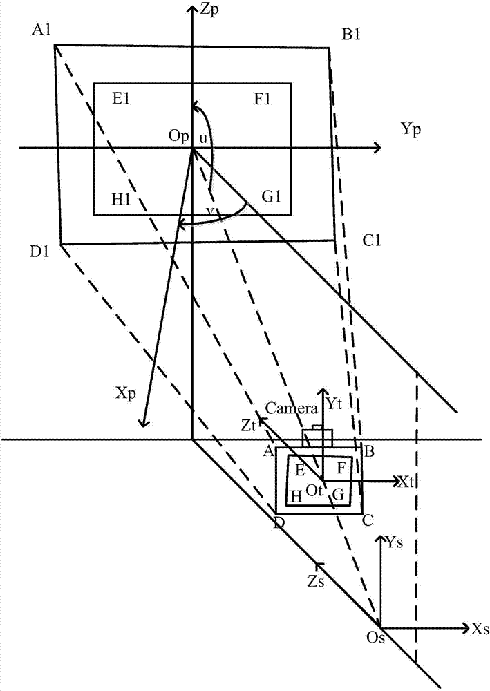
[0054] refer to figure 1 , is a schematic diagram of a projection system in this application. In the embodiment of the present application, the screen is set on the wall, and the light source projects the original image onto the screen on the wall through the lens. The projector is usually placed below the screen and some distance away from the wall. Of course, the projector can also be placed parallel to the center of the screen. This application does not limit the location where the projector is placed.

[0055] On the screen, take the point Op where the projector light source Os reaches the wall through the lens center as the coordinate origin, establish the first coordinate system OpXpYpZp, the Xp...


PUM


Abstract

The invention discloses a projection imaging correction method and apparatus, and a laser TV. The embodiment of the invention provides a projection imaging correction method, comprising the followingsteps: obtaining a specified area image, wherein the specified area image comprises a projection mage of an original image and a screen image, the specified area image has a first coordinate system, and the original image has a second coordinate system; obtaining a first conversion relation of the first coordinate system and the second coordinate system; calculating vertex angle coordinates of theprojection mage of the original image, and the vertex angle coordinates of the screen image; calculating a target image coordinate by using the first conversion relation, the vertex angle coordinatesof the projection mage of the original image and the vertex angle coordinates of the screen image; and using the target image coordinate to correct the original image. According to the embodiment ofthe invention, no user operation is needed, so that the projection system can be debugged without a professional debugger.

Description

technical field [0001] The present application relates to the technical field of image processing, in particular to a projection imaging correction method, a projection imaging correction device and a laser television. Background technique [0002] The current projection system generally consists of a projector and a screen. A projector projects an image onto a screen, and alignment of the projector's projected image with the screen is usually a manual process. For professional debuggers, precise alignment is a relatively time-consuming and cumbersome process, and for ordinary users who are not familiar with projection equipment, it is even more difficult. Contents of the invention [0003] In view of the above problems, the embodiments of the present application are proposed to provide a projection imaging calibration method, a projection imaging calibration device, and a laser television that overcome the above problems or at least partially solve the above problems. ...

Claims


Application Information

Patent Timeline
Patent Type & Authority Applications(China)
IPC IPC(8): H04N9/31
Inventor 钟声
Owner 上海顺久电子科技有限公司
Why Eureka
Try Eureka