
Driving circuit board and displaying device

A technology for driving circuit boards and display devices, which is applied to circuits, printed circuits, printed circuits, etc., and can solve the problems of reduced curvature at the bend of the drive circuit board, increased length of the drive circuit board, and increased bending resistance , to achieve the effects of reducing the bending resistance, increasing the bending curvature, and reducing the bending radius

Active Publication Date: 2018-01-05
BOE TECH GRP CO LTD +1
View PDF4 Cites 5 Cited by
  • Summary
  • Abstract
  • Description
  • Claims
  • Application Information

AI Technical Summary

Problems solved by technology

Due to the increase in the size of the display device and the increase in resolution, the number of leads on the display substrate increases, and the length of the driving circuit board increases accordingly, resulting in an increase in the bending resistance, thereby reducing the curvature of the bending part of the driving circuit board and reducing the bending. The radius increases, which is not conducive to the realization of narrow borders

Method used


Image

  • Driving circuit board and displaying device
  • Driving circuit board and displaying device
  • Driving circuit board and displaying device

Examples


Embodiment Construction

[0026] Specific embodiments of the present invention will be described in detail below in conjunction with the accompanying drawings. It should be understood that the specific embodiments described here are only used to illustrate and explain the present invention, and are not intended to limit the present invention.

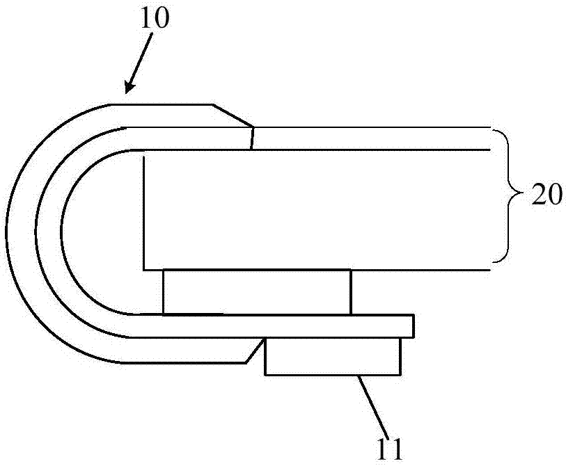
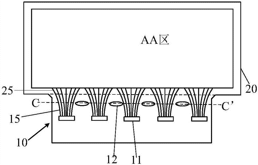
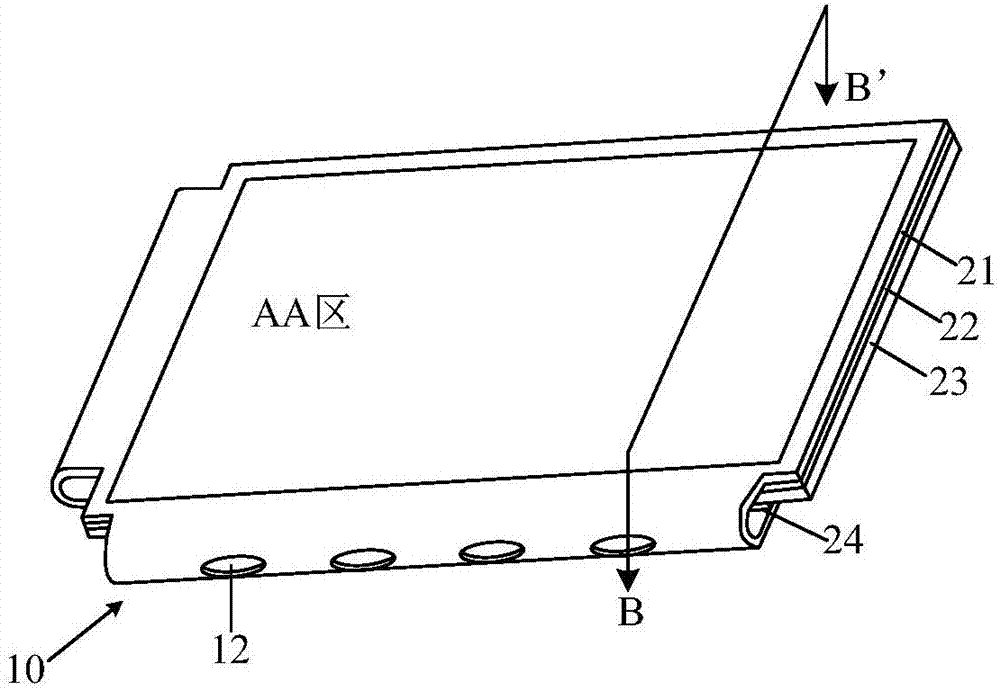
[0027] As one aspect of the present invention, a driving circuit board 10 is provided, the driving circuit board 10 is used in a display device, and the display device includes a display substrate 20, and the display substrate 20 includes a display area (AA area) and is located in the display area ( AA region) around the lead region, the lead region is provided with leads extending from the display region. One end of the driving circuit board 10 is used for electrical connection with the lead area, and the driving circuit board 10 can be bent, and the other end of the driving circuit board 10 is located on the side of the display substrate 20 away from the light...


PUM


Abstract

The invention provides a driving circuit board. The driving circuit board is applied to a displaying device. The displaying device board comprises a displaying substrate, the displaying substrate comprises a displaying area and a lead area located around the displaying area, and the lead area is provided with a lead which extends from the displaying area; one end of the driving circuit board is used for being electrically connected with the lead of the lead area, the driving circuit board can be bent, and the other end of the driving circuit board is located at the side, deviating from the light emergence direction, of the displaying substrate; the driving circuit board is provided with through holes running through the driving circuit board, and the through holes are located on the bending portion of the driving circuit board. Correspondingly, the invention further provides the displaying device. The driving circuit board is easier to bend, and therefore a narrow frame of the displaying device is easily achieved.

Description

technical field [0001] The invention relates to the field of display technology, in particular to a driving circuit board and a display device. Background technique [0002] Organic light-emitting devices (Organic Light-Emitting Device, OLED) have the advantages of active light emission, good temperature characteristics, low power consumption, fast response, wide viewing angle, ultra-thin and low cost, and have been widely used in display devices. In organic electroluminescent display devices, such as figure 1 As shown, the driving chip 11 is disposed on the driving circuit board 10 , and is electrically connected to the lead wires on the display substrate 20 through the signal lines on the driving circuit board, so as to provide driving signals for the display substrate 20 . After one end of the driving circuit board 10 is connected to the display substrate 20 , it is bent toward the side of the display substrate 20 away from the light emitting direction, so that the other...

Claims


Application Information

Patent Timeline
Patent Type & Authority Applications(China)
IPC IPC(8): H01L27/32G09G3/3208
CPCG09G3/3208H05K1/028H05K2201/10128H05K1/189H05K2201/09063H01L25/18
Inventor 冯彬峰
Owner BOE TECH GRP CO LTD
Learn More