Sending device for material pneumatic conveying system

A technology of pneumatic conveying and sending device, applied in the direction of conveyor, transportation and packaging, etc., can solve the problems of inability to judge the coding information of the object to be conveyed, inability to realize multi-point automatic transmission, and large size of the sending station, so as to facilitate the transmission operation. , Small footprint, high work efficiency

Pending Publication Date: 2018-01-05
HUNAN SUNDY SCI & TECH DEV
View PDF5 Cites 1 Cited by
  • Summary
  • Abstract
  • Description
  • Claims
  • Application Information

AI Technical Summary

Problems solved by technology

[0005] (1) The existing technology adopts the lifting method to push the object (sample bottle) into the pneumatic pipeline or lowers the conveying pipe to cover the object (sample bottle) by lifting method, which makes the control complicated, the sealing requirement is high, and it is easy to appear Fault
[0006] (2) The existing technology adopts the lifting method, and the bottom or upper part of the sending station needs to be reserved for lifting and displacement space, and the airborne requirements are large, resulting in a generally large sending station
[0007] (3) In the prior art, the sample bottle needs mechanism control from the placing station to the sending station, and the sending of the sample bottle on the sending station needs another lifting mechanism to place the sample bottle into the pipeline first, and the control is complicated
[0008] (4) There is no card reader at the bottom of the existing technology, and it is impossible to judge the code information of the object (sample bottle) to be transported, and the system cannot automatically send the sample bottle to which workstation
Unable to realize multi-point automatic transmission

Method used


Image

  • Sending device for material pneumatic conveying system
  • Sending device for material pneumatic conveying system
  • Sending device for material pneumatic conveying system

Examples


Embodiment Construction

[0031] The present invention will be described in further detail below in conjunction with specific embodiments and accompanying drawings.

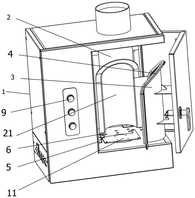
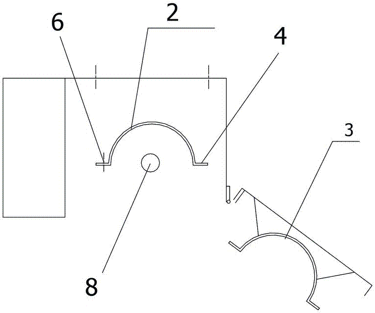
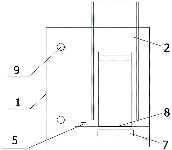
[0032] Such as Figure 1 to Figure 4 As shown, the present invention provides a sending device for a material pneumatic conveying system, comprising a frame 1, a sending station 11 is provided in the frame 1, and a vertical sending pipeline 2 is provided at the sending station 11 for use in In connection with the pneumatic transmission pipeline, the side wall of the lower end of the sending pipeline 2 is provided with a sample delivery notch 21 for placing the object to be transported at the sending station 11, and is also provided with a matching hole 21 for the sample delivery notch 21. The sample delivery door 3 is used to close the sample delivery gap 21 for pneumatic delivery. In this embodiment, the sample delivery door 3 is hingedly installed on the frame 1, and in other embodiments, it can also be closed manually or translated in...


PUM


Abstract

The invention discloses a sending device for a material pneumatic conveying system. The sending device comprises a machine frame, wherein a sending station is arranged in the machine frame; the sending station is provided with a vertical sending pipeline for communicating with a pneumatic conveying pipeline; a sample feeding notch is formed in the side wall of the lower end of the sending pipelineso that an object to be conveyed can be placed at the sending station; and a sample feeding door matched with the sample feeding notch is further arranged, so that the sample feeding notch is sealedafter the sample feeding door is closed so as to carry out pneumatic sending. The sending device for the material pneumatic conveying system has the advantages of being simple and compact in structure, convenient and flexible to operate, high in working efficiency and intelligent degree.

Description

technical field [0001] The invention mainly relates to the field of equipment for collecting and processing material samples, and in particular to a sending device for a material pneumatic conveying system. Background technique [0002] For the sampling, sample preparation, and testing of material (such as ore, coal) samples, each country has mandatory standards, and the sampling and processing of samples must be carried out in accordance with the standards. The principle of sample sampling, sample preparation, and testing work process is to gradually reduce the particle size and quality of the collected samples without destroying the representativeness of the sample, until it meets the particle size and quality of the sample in the laboratory test ( Weight) accuracy requirements, and then carry out relevant laboratory analysis on the samples that meet the requirements. [0003] For example, taking coal sampling as an example, it is actually a sampling and analysis process....

Claims


Application Information

Patent Timeline
IPC IPC(8): B65G51/28B65G51/40
Inventor 李冬军肖兵球
Owner HUNAN SUNDY SCI & TECH DEV
Why Eureka
Try Eureka