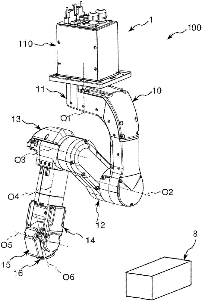
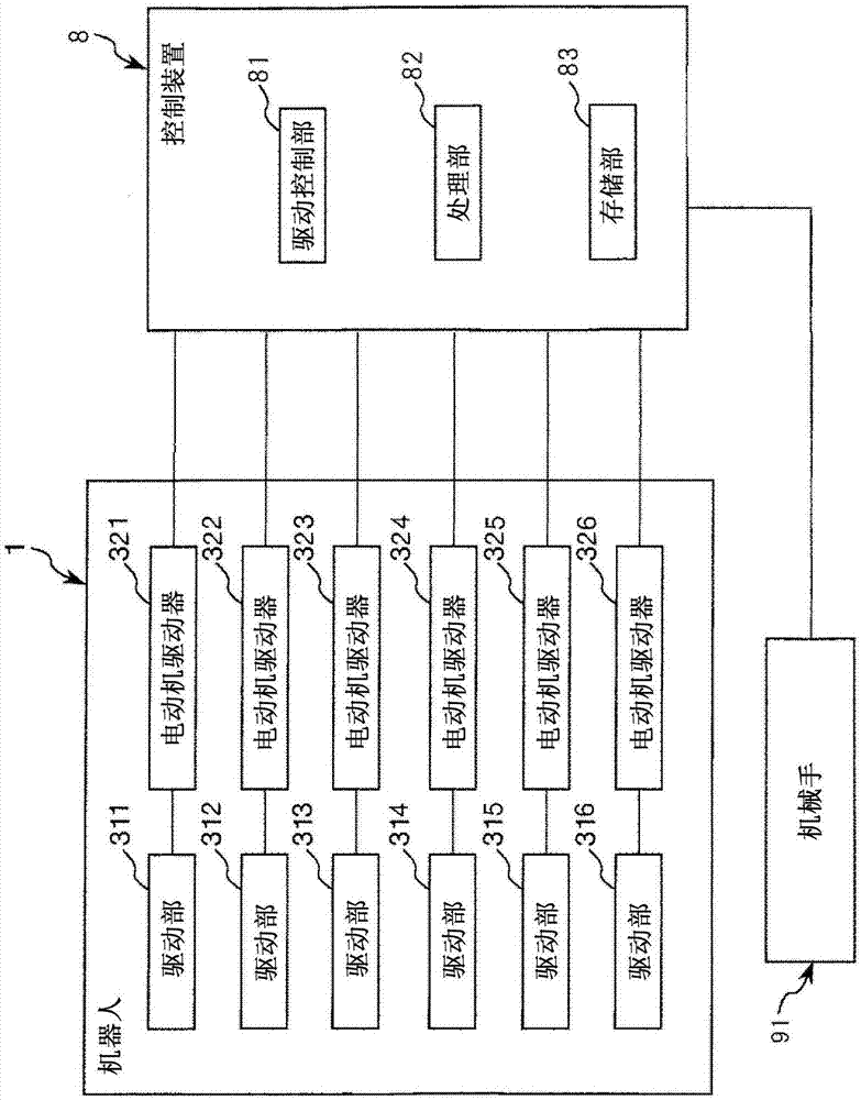
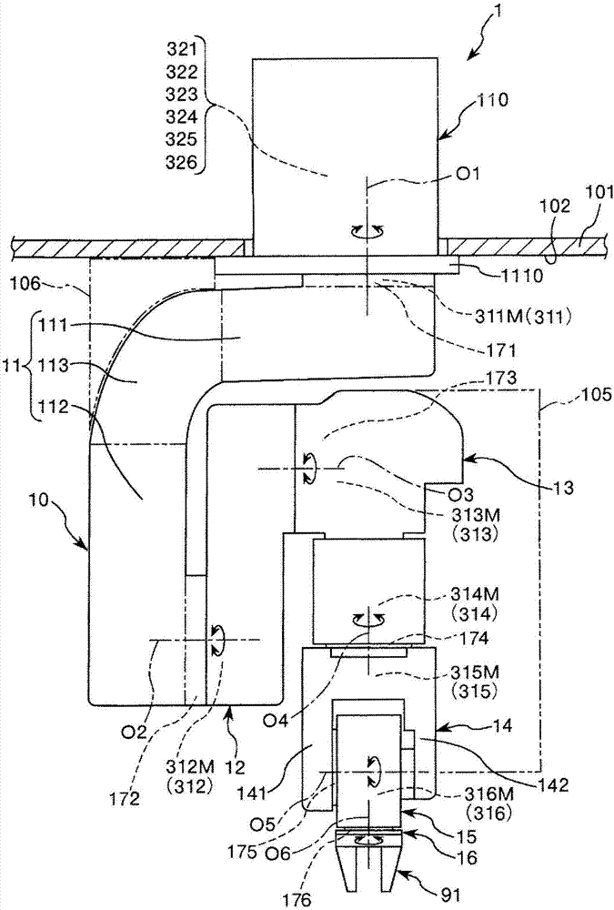
Robot, control device, and robot system
一种机器人、部件的技术,应用在程序控制机械手、机械手、制造工具等方向,能够解决断线等问题
- Summary
- Abstract
- Description
- Claims
- Application Information
AI Technical Summary
Problems solved by technology
Method used
Image

Examples
no. 2 approach >
[0131] Figure 13 It is a figure which shows the bundle|flux of the flexible member which the robot concerning 2nd Embodiment of this invention has. Figure 14 is used to describe the Figure 13 A diagram of the configuration of the identification marks on the bundle of flexible components shown in .
[0132] Next, the second embodiment will be described, but the description will focus on the differences from the above-mentioned embodiment, and the description of the same matters will be omitted. It should be noted that in Figure 13 The illustration of the flange 125 is omitted in FIG. Figure 14 The illustrated bundle 5 shows a state not attached to the frame 332 (state before attachment).
[0133] exist Figure 13 The flexible member 52 included in the illustrated bundle 5 has identification marks 71 and 72 for distinguishing the appearance of the flexible member 52 from the appearance of the other flexible members 51 , 53 to 56 . Such as Figure 14 As shown, the ide...
PUM
 Abstract
Description
Claims
Application Information
 - Generate Ideas
- Intellectual Property
- Life Sciences
- Materials
- Tech Scout
- Unparalleled Data Quality
- Higher Quality Content
- 60% Fewer Hallucinations
Browse by: Latest US Patents, China's latest patents, Technical Efficacy Thesaurus, Application Domain, Technology Topic, Popular Technical Reports.
© 2025 PatSnap. All rights reserved.Legal|Privacy policy|Modern Slavery Act Transparency Statement|Sitemap|About US| Contact US: help@patsnap.com