
Cavity sealing

An airfoil, metal material technology, applied in electron beam welding equipment, non-electric welding equipment, laser welding equipment, etc., can solve the problems of difficult quality control of opening fillers, insufficient chemical resistance and heat resistance of damping materials, etc.

Inactive Publication Date: 2018-01-05
ROLLS ROYCE PLC
View PDF8 Cites 0 Cited by
  • Summary
  • Abstract
  • Description
  • Claims
  • Application Information

AI Technical Summary

Problems solved by technology

However, the use of such fillers, glues, Resin, composite, polymeric or elastomeric material is problematic
Additionally, quality control of the opening filling that forms the plug is difficult
This leads to the possibility of the plug falling out of the opening after insertion due to, for example, different thermal expansion coefficients and thus different thermal expansions between the opening filling and the component

Method used


Image

  • Cavity sealing
  • Cavity sealing
  • Cavity sealing

Examples


Embodiment Construction

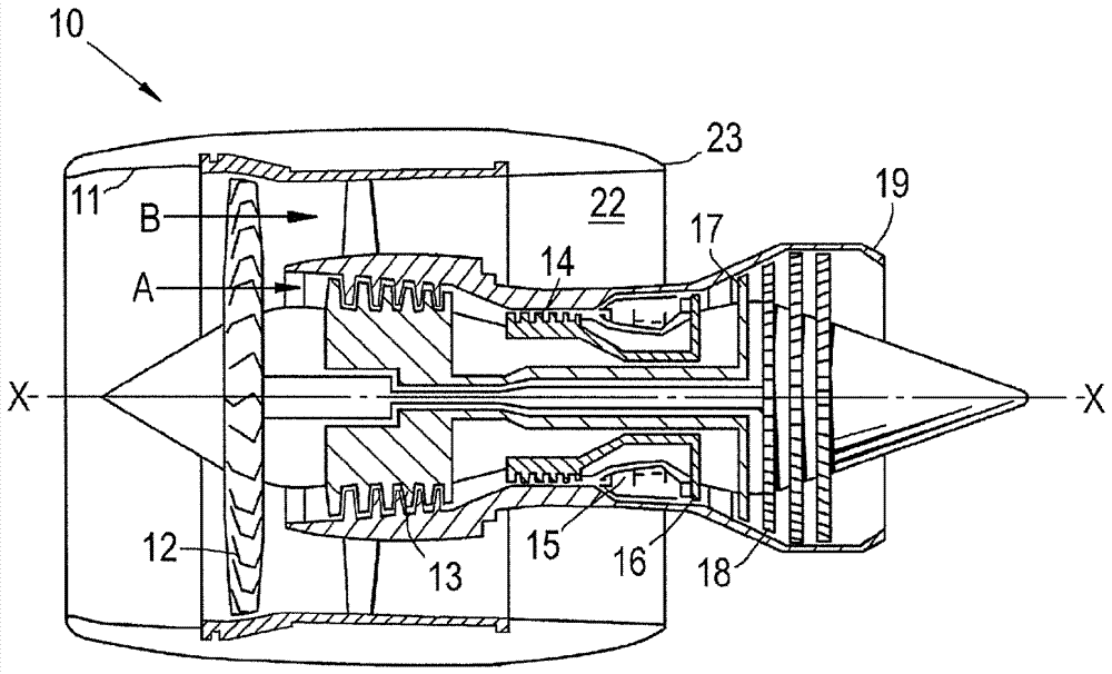
[0058] refer to figure 1 , a ducted fan gas turbine engine generally indicated by 10 has a principal and axis of rotation X-X. The engine 10 comprises, in axial sequence, an air intake 11, a propulsion fan 12, an intermediate pressure compressor 13, a high pressure compressor 14, a combustion equipment 15, a high pressure turbine 16, and an intermediate pressure turbine 17, a low pressure turbine 18 and a core engine discharge nozzle 19. The engine also has a bypass duct 22 and a bypass discharge nozzle 23 .

[0059] The gas turbine engine 10 operates in a conventional manner so that air entering the air intake 11 is accelerated by the fan 12 to generate two air flows: a first air flow A entering the intermediate pressure compressor 13 and passing through a bypass duct 22 to provide The second air flow B for propulsion thrust. The medium pressure compressor 13 compresses the air flow A introduced thereto before delivering this air to the high pressure compressor 14 where fu...


PUM


Abstract

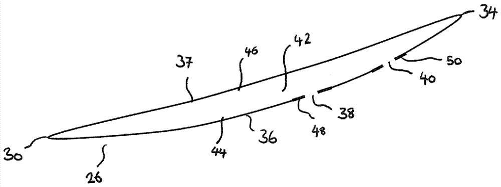
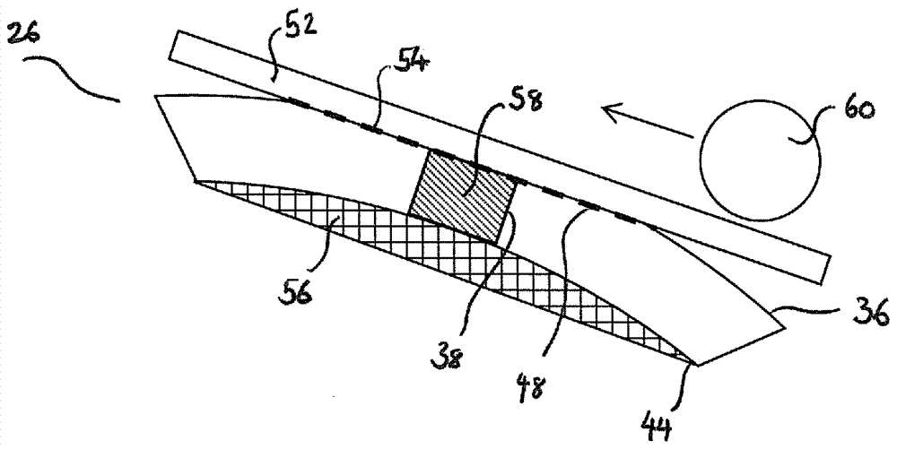
The invention relates to cavity sealing. A method of sealing one or more openings provided in a wall of an aerofoil for a gas turbine engine is provided, the aerofoil comprising at least one cavity which is at least partly filled with a vibration damping material. The method comprises the steps to provide a metallic material onto the wall of the aerofoil in order to cover the opening and bond themetallic material to the wall of the aerofoil to seal the opening.

Description

technical field [0001] The present invention relates to methods and apparatus for sealing cavities in aerospace components. In particular, it relates to methods and apparatus for providing metallic material onto an airfoil for sealing cavities. Background technique [0002] It is known to use hollow airfoils, or airfoils comprising one or more cavities, in order to provide weight saving advantages. Some cavities can be formed by inflating an airfoil precursor at a superplastic temperature. At least one of the cavities usually includes an internal metallic structure to increase strength and prevent so-called panting, ie movement towards and away from each other, of the walls of the airfoil. [0003] To facilitate damping and reduce vibration of the component, the hollow cavity may be filled with a damping material, such as a viscoelastic material. The cavity wall may include one or more protrusions that provide additional surface area to increase adhesion between the dampi...

Claims


Application Information

Patent Timeline
Patent Type & Authority Applications(China)
IPC IPC(8): B23K20/10B23K26/21B23K15/00
CPCB22F5/04B22F7/08B23P6/002F01D5/005F01D5/16F01D5/28F04D29/083F04D29/324F04D29/668F05D2230/233F05D2230/234F05D2230/31F01D5/147B22F3/10B23K20/10F01D5/26F04D29/388F05D2220/32
Inventor P.J.多尔巴
Owner ROLLS ROYCE PLC
Learn More