Structure for increasing riser feeding distance and provided with gas forming block at top of riser
A gas block and riser technology is applied in the structural field where a gas block is arranged on the top of the riser to increase the feeding distance of the riser. , the effect of improving liquidity
Inactive Publication Date: 2018-01-05
KEHUA HLDG
View PDF8 Cites 1 Cited by
- Summary
- Abstract
- Description
- Claims
- Application Information
AI Technical Summary
Benefits of technology
This technology allows for efficient use of molasses during production while maintaining good flow properties through an immersion nozzle system used in roll castings. By melting outer layers off one side of each other at certain points along its length, it becomes more liquid-like before being forced downwardly towards another area where there are fewer parts needed. Additionally, if some areas have been damaged or worn out due to wear overtime, these cracks can be repaired quickly without causing any problems like leakage from the device's valve. Overall, this process helps improve efficiency and productivity in manufacturing processes.
Problems solved by technology
This patented technical problem addressed in this patents relates to improving casting efficiency for engines with turbines that use multiple valves arranged along their length. Specifically, there can exist variations where different components within these systems require precise placement during manufacturing due to differences in temperature conditions when they melt down into liquid metal. These issues lead to difficulties in achieving efficient flow through various areas such as pipelines, manifolds, nozzles, etc., leading to reduced production rates and increased costs associated with maintenance work on those affected devices.
Method used
View moreImage
Smart ImageViewing Examples

Examples
Embodiment Construction
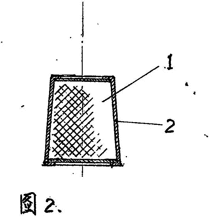
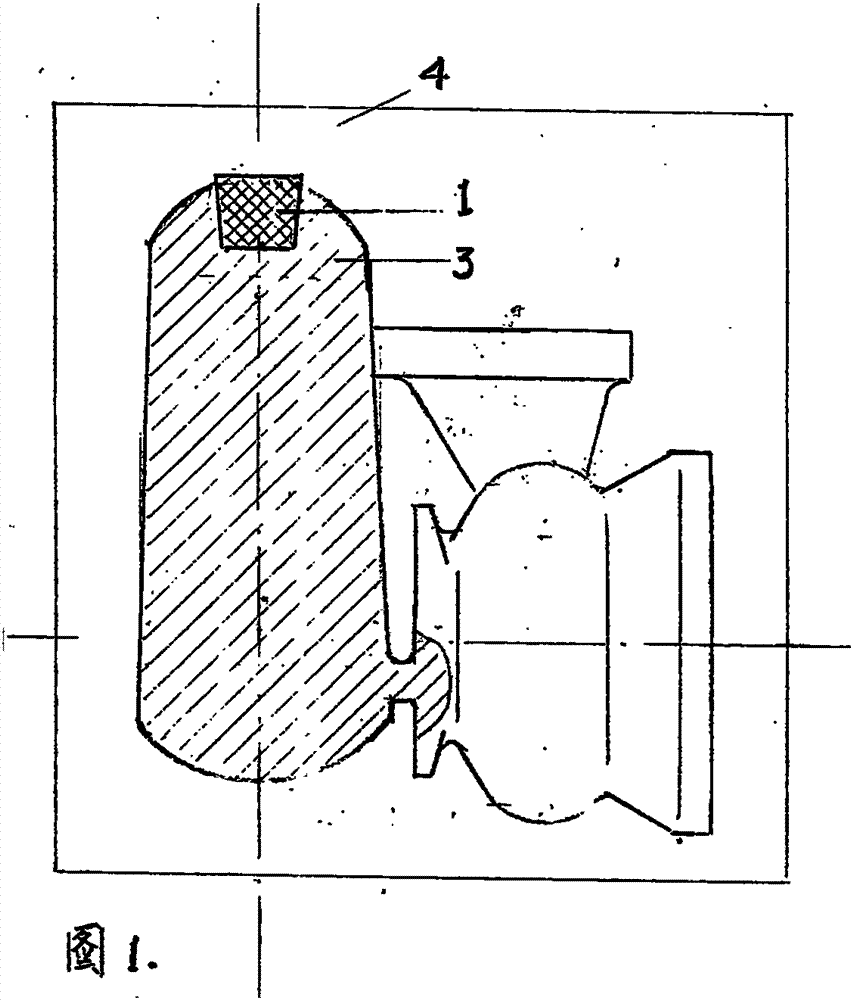
[0009] A structure in which an air-generating block is arranged on the top of the riser to increase the feeding distance of the riser.
[0010] The gas generating block 1 is placed on the top of the riser 3 on the side of the volute outer mold 4, and a thin steel plate cladding layer 2 is coated on the outside of the gas generating block 1.
Login to View More PUM
 Abstract
The invention is a structure that increases the feeding distance of the riser and arranges an air generating block on the top of the riser. When the common side riser is used to feed the inside of the volute, the purpose of feeding cannot be achieved due to the long distance between the riser neck and the feeding part. Now the top of the riser is provided with an air-generating block, and a thin steel plate is covered outside the air-generating block. After the gas generating block contacts the molten iron, it will generate heat and generate gas when heated, which can increase the fluidity of the riser molten iron and move to the feeding part. At the same time, the gas generating block is blocked by the thin steel plate to prevent the molten iron from being heated too quickly. The feeding effect of the riser is normal, and the casting can be effectively fed.
Description
Login to View More Claims
Login to View More Application Information
Patent Timeline
 Owner KEHUA HLDG
Features
- Generate Ideas
- Intellectual Property
- Life Sciences
- Materials
- Tech Scout
- Unparalleled Data Quality
- Higher Quality Content
- 60% Fewer Hallucinations
Learn More Browse by: Latest US Patents, China's latest patents, Technical Efficacy Thesaurus, Application Domain, Technology Topic, Popular Technical Reports.
© 2025 PatSnap. All rights reserved.Legal|Privacy policy|Modern Slavery Act Transparency Statement|Sitemap|About US| Contact US: help@patsnap.com