
A component handling assembly

A technology for parts and assemblies, applied in the field of parts processing assemblies, which can solve problems such as part displacement

Inactive Publication Date: 2018-01-02
RASCO
View PDF12 Cites 0 Cited by
  • Summary
  • Abstract
  • Description
  • Claims
  • Application Information

AI Technical Summary

Problems solved by technology

Therefore, if the carrier is only sparsely occupied by components, the risk of possible displacement of the components due to acceleration forces during transport of the carrier increases

Method used


Image

  • A component handling assembly
  • A component handling assembly
  • A component handling assembly

Examples


Embodiment Construction

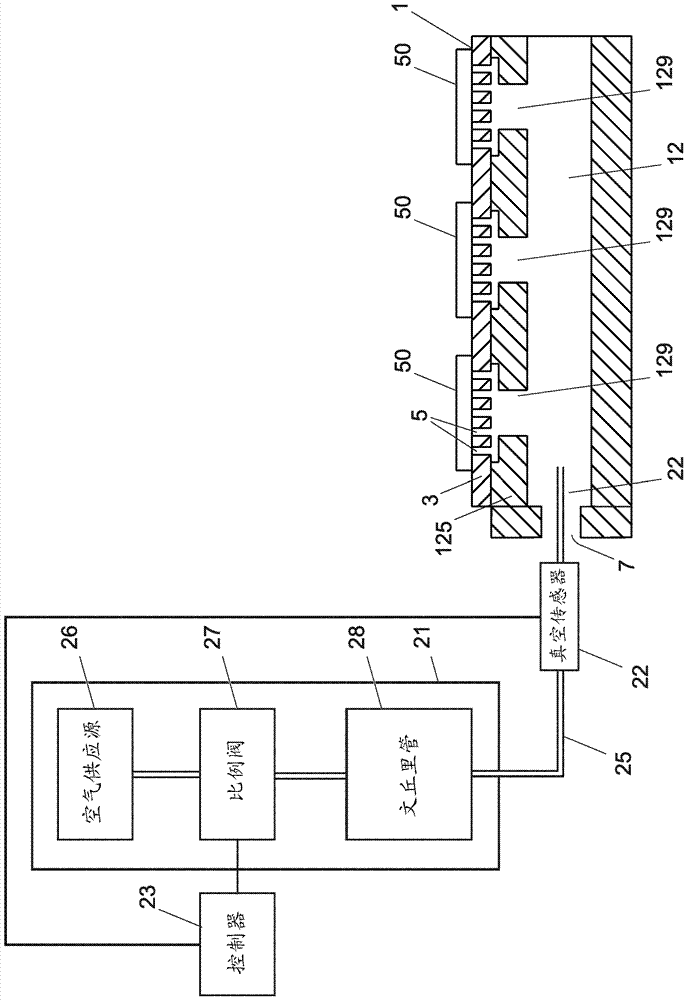
[0077] figure 1 A simplified longitudinal cross-sectional view of a portion of an exemplary carrier 1 that may be used in a parts handling assembly according to an embodiment of the invention is provided. In this example, the carrier 1 takes the form of a boat hull 1 . The carrier 1 comprises a surface 3 on which a plurality of components 50 have been loaded. The surface 3 has defined therein a plurality of holes 5 through which a vacuum can pass to hold the component 50 on the surface 3 .

[0078] exist figure 2 In the exemplary embodiment shown in , surface 3 is defined by metal layer 123 . Preferably, the metal layer 123 has a thickness "T" between 0.3 mm-2 mm; and the metal layer 123 preferably comprises a metal sheet. For example, metal layer 23 may comprise any suitable material, such as aluminum alloy, steel, copper alloy, glass, silicon. A hole 5 is defined in the metal layer 123 . Preferably, the holes 5 are formed in the metal layer 123 by drilling or etching....


PUM


Abstract

According to the present invention there is provided a component handling assembly () suitable for facilitating loading or unloading a plurality of components onto / from a carrier. The assembly comprises: a carrier (1) which comprises a surface (3) on which a plurality of components (50) can be supported, wherein the surface (3) has a plurality of holes (5) defined therein; a vacuum generator (21)which can be arranged in fluid communication with the plurality of holes (5) in the surface (3) of the carrier (1) so that a vacuum can be applied, through the plurality of holes (5), to components (50) supported on the surface (3) of the carrier (1), to hold components (50) on the surface (3) of the carrier (5); and a vacuum sensor (22) for sensing the level of vacuum applied to components (50) supported on the surface (3) of the carrier; a controller (23) for controlling the vacuum generator (21) during loading and / or unloading of component(s) onto / from the surface (3) of the carrier, basedon the level of vacuum sensed by the vacuum sensor (22), so that a predefined level of vacuum is applied to component(s) (50) supported on the surface (3) during loading and / or unloading of component(s) (50) onto / from the carrier (1). There is further provided a corresponding method of handling components (50).

Description

technical field [0001] The present invention relates to a component handling assembly, and in particular to a component handling assembly in which a component is applied to a component supported on a surface of a carrier to retain the component on said surface. The vacuum level on the surface remains substantially constant while loading additional components onto the surface and / or remains substantially constant while unloading additional components from the surface. Background technique [0002] Typically, in existing component handling assemblies, the components are held on the carrier by mechanical means. In other part handling assemblies, the part is held on the carrier by means of a vacuum; in this case, the surface of the carrier includes holes (vacuum holes) and the vacuum is applied through these holes to the parts supported on the surface of the carrier. Part; the vacuum force holds the part on the surface of the carrier. [0003] When the part is placed on the su...

Claims


Application Information

Patent Timeline
Patent Type & Authority Applications(China)
IPC IPC(8): H01L21/683H05K13/04B65G47/91G01R31/28
CPCB65G47/917G01R31/2893H05K13/0409H05K13/082H05K13/041G01R31/2867H01L21/6838H05K13/0408
Inventor R.希特曼恩M.肖勒D.施米德
Owner RASCO
Learn More