System
一种系数、检测值的技术,应用在系统领域,能够解决延迟火灾检测等问题
- Summary
- Abstract
- Description
- Claims
- Application Information
AI Technical Summary
Problems solved by technology
Method used
Image


Examples
no. 1 example
[0246] First, the first embodiment will be described. The first embodiment is an embodiment of judging whether an abnormality occurs according to the detection value of the smoke sensor, the detection value of the carbon monoxide sensor, the first coefficient, and the judgment threshold.
[0247] (structure)
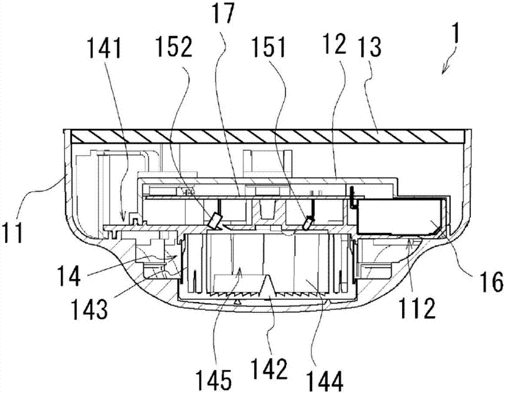
[0248] First, the configuration of the detector will be explained according to the first embodiment. figure 1 It is a schematic diagram showing the appearance of the detector according to the first embodiment. figure 1 (a) is a perspective view showing the state of the detector mounted on the ceiling from the lower side. figure 1 (b) is a side view of the detector. figure 1 (c) Bottom view of the state of the detector mounted to the ceiling from the lower side. It should be noted that although figure 1 (c) The smoke sensor 15 and the carbon monoxide sensor 16 are not actually visible, but are shown in dashed lines for ease of description (also applies to the followi...
no. 2 example
[0346] Hereinafter, the second embodiment will be described. The second embodiment is an embodiment of judging whether an abnormality occurs according to the detection value of the smoke sensor, the detection value of the carbon monoxide sensor, the first coefficient, the second coefficient and the judgment threshold. It should be noted that the configuration of the second embodiment is substantially the same as that of the first embodiment unless otherwise specified. If necessary, any configuration that is the same as that of the first embodiment is given the same symbol as that used in the first embodiment, and the description thereof is omitted.
[0347] (structure)
[0348] First, the configuration of a detector according to the second embodiment will be explained. Figure 10 It is a schematic diagram of the appearance of the detector according to this embodiment. Figure 10 (a) is a perspective view showing the state of the detector mounted on the ceiling viewed from t...
no. 3 example
[0391] The third embodiment will be described below. The third embodiment is to determine whether an abnormal situation occurs according to the detection value of the smoke sensor, the detection value of the carbon monoxide sensor, the first coefficient, and the judgment threshold. The detection value of the device is used for judgment. It should be noted that the configuration of the third embodiment is substantially the same as that of the first embodiment unless otherwise specified. If necessary, any configuration that is the same as that of the first embodiment is given the same symbol as that used in the first embodiment, and the description thereof is omitted.
[0392] (structure)
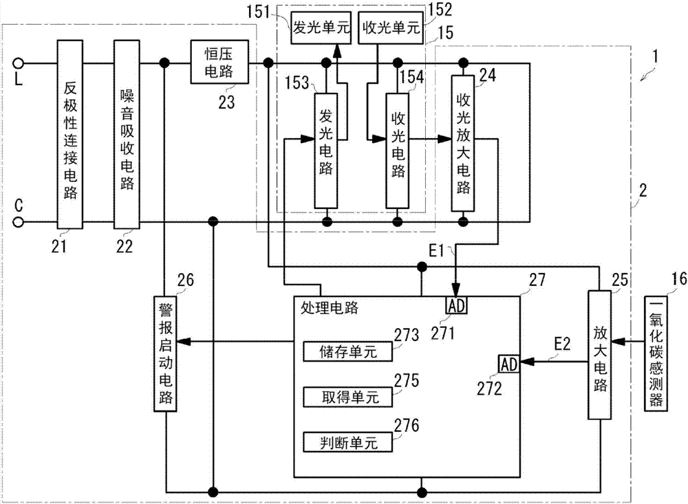
[0393] First, since the detector according to this embodiment has the same appearance as the detector in the first embodiment, only the electrical configuration of the detector is described. Figure 17 A block diagram of a detection circuit according to this embodiment is shown.
[0394] ...
PUM
 Abstract
Description
Claims
Application Information
 - R&D
- Intellectual Property
- Life Sciences
- Materials
- Tech Scout
- Unparalleled Data Quality
- Higher Quality Content
- 60% Fewer Hallucinations
Browse by: Latest US Patents, China's latest patents, Technical Efficacy Thesaurus, Application Domain, Technology Topic, Popular Technical Reports.
© 2025 PatSnap. All rights reserved.Legal|Privacy policy|Modern Slavery Act Transparency Statement|Sitemap|About US| Contact US: help@patsnap.com