A washing machine solenoid valve energy-saving circuit

An energy-saving circuit, solenoid valve technology, applied in valve details, valve devices, mechanical equipment, etc., can solve the problems of small diameter coil solenoid valves easily damaged, high cost of double coils, and difficult winding, etc., to reduce The effect of working current, prolonging service life and reducing heat generation

Active Publication Date: 2019-04-30
HUNAN SHUI KOU SHAN NONFERROUS METALS GRP
View PDF4 Cites 0 Cited by
  • Summary
  • Abstract
  • Description
  • Claims
  • Application Information

AI Technical Summary

Problems solved by technology

Although this design solves the problem of the pull-in distance of the solenoid valve, it is necessary to design a component that controls the action of the micro switch. The design of this component is not easy; and the pull-in coil still needs to be wound with a small diameter enameled wire its service life
[0004] To sum up, conventional coils used in the prior art have the disadvantages of difficult winding, high energy consumption, and the coil is prone to heating and damage. Although the double coil solves the energy-saving problem of the solenoid valve, the cost of the double coil is relatively high. Moreover, the solenoid valve of the small-diameter coil is easily damaged

Method used


Image

  • A washing machine solenoid valve energy-saving circuit

Examples


Embodiment Construction

[0015] The present invention will be further described in detail below in conjunction with the accompanying drawings and specific embodiments.

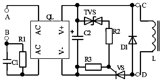
[0016] Such as figure 1 Shown: a washing machine solenoid valve energy-saving circuit, composed of thyristor trigger circuit, thyristor VS, solenoid valve coil L and diode D1. The thyristor trigger circuit is constructed by current limiting capacitor C1, rectifier bridge QL, energy storage capacitor C2, TVS tube (transient voltage suppressor diode) and resistors R1, R2, and R3. The specific line relationship connection is as follows:

[0017] One end of the current-limiting capacitor C1 is used as a terminal of the solenoid valve to connect to the terminal B of the solenoid valve control circuit of the washing machine, the other end of the current-limiting capacitor C1 is connected to an AC input terminal AC of the rectifier bridge QL, and the other AC input terminal of the rectifier bridge is connected to AC Terminal A of the solen...


PUM


Abstract

The invention discloses an electromagnetic valve energy-saving circuit of a washing machine. The electromagnetic valve energy-saving circuit comprises a silicon controlled rectifier trigger circuit, a silicon controlled rectifier, an electromagnetic valve coil and a diode. The silicon controlled rectifier trigger circuit comprises a current limiting capacitor, a rectification unit, an energy storage capacitor, a TVS (transient voltage suppressor) diode and resistors R1, R2 and R3; one end of the current limiting capacitor is used as a terminal of an electromagnetic valve to be connected with one end of an electromagnetic valve control circuit, the other end of the current limiting capacitor is connected with an alternating-current input end of the rectification unit, and another alternating-current input end of the rectification unit is connected with the other end of the electromagnetic valve control circuit; a direct-current output end of the rectification unit is connected with the energy storage capacitor; one end of the TVS diode is connected with a positive electrode of the energy storage capacitor, and the other end of the TVS diode is connected with a control electrode of the silicon controlled rectifier by the resistor R2 which is serially connected with the TVS diode; the silicon controlled rectifier is further connected with the resistor R3; a cathode of the silicon controlled rectifier is further connected with the direct-current output end of the rectification unit; an anode of the silicon controlled rectifier is connected with an anode of the diode, and a cathode of the diode is connected with the direct-current output end of the rectification unit. The electromagnetic valve energy-saving circuit has the advantages that the electromagnetic valve energy-saving circuit is low in cost, energy can be saved, consumption can be reduced, and the coil is long in service life.

Description

technical field [0001] The invention relates to a washing machine control system, in particular to an energy-saving circuit for a washing machine electromagnetic valve. Background technique [0002] In order to achieve the purpose of energy saving, the existing solenoid valves for washing machines generally use thin-diameter enameled wires or double-coil structures. The length of the enameled wire is hundreds of meters to nearly a thousand meters), the production cost is high, and it is easy to be damaged. Especially for washing machines used in humid environments, since the pull-in current is the same as the holding current, the coil is prone to heating and damage. In addition, due to the small diameter of the wire, the working current of the solenoid valve is small, and this kind of solenoid valve has disadvantages such as short pull-in distance and short service life. [0003] In order to solve the above problems, a double-coil solenoid valve has also appeared in the pr...

Claims


Application Information

Patent Timeline
Patent Type & Authority Patents(China)
IPC IPC(8): F16K31/06
CPCF16K31/0675
Inventor 王学文周奉娟
Owner HUNAN SHUI KOU SHAN NONFERROUS METALS GRP
Why Eureka
Try Eureka